I use LM3886 only with a gain of 2.8. It needs 180/100 ohms feedbacks in non inverting mode. For the voltage gain ,I use 600:10k good quality (24$ a pair) transformer. I see on YouTube Live distortion measured of LM1875 0.011% most probably with gain of application circuit 26db. If running at gain of 6db you have an extra zero in the above number.
Thanks for the info!
Have you tried the 3886 inverting? That's the cool and performance increasing part I like. Without a buffer you'd want something easily driven on Rin like 10k (Rfb=30k)
Do you think that would work, could you give it a try?
If Rin and Rfb need to be small, a good buffer on the input would allow more options.
Thanks and cheers,
Jeff
Look at post 59 . I used inverted with gain of 3 with high impedance to be driven by ECC82 in composite. The sound of non inverting with low impedance feedback is far superior.ANDREA a Democratic hybrid amp for luxury sound
.........................
I recall that the + and - inputs want to see the same resistance (and parallel capacitance) for the best balance and improved performance.
So the negative input will see Ri (2.2k) in series with the output impedance of the previous stage (usually ~100R), so 2.3k. That's in parallel with Rfb (4.7k) so 2.3k||4.7k=1.54k
Thus Rn should be 1.54k too (1% resistors or 5% measured).
PS Does this circuit work with the LM3886/LM3887 or one of the other good chip amps? The extra power (if needed) would make this superb!
PPS Putting a decent buffer on the input will isolate (better performance) it from the previous stage.

I was surprised the low gain coupling was so stable after the explicit different guidance in the datasheet. Evidently, when implementing low gain versions we are outside of the datasheet and have to check everything our self.
The trick with equal impedance for the two inputs I learned to be a remedy not to increase offset caused by common mode currents from the two input lines. With low impedance values the contribution is little and I just used 1K not to bother when I changed the feedback resistors.
I have no experience with LM3886 but kokoriantz has good experience. As many datasheets state stability above 20dB gain, I believe that chip-amps are often compensated in a similar manner and the same low gain versions can be used.
You are generally right with input buffers. But, as a buffer used here will be inside a composite amplifier regulation loop in the end, I prefer the elements that can "pollute" the transfer function to be as few as possible in this particular case.
Last edited:
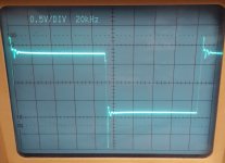
I put a +/-24Vdc power supply on the LM1875 amplifier and swapped between inverting and non inverting configuration using the same gain setting resistors. I could get to +/-20V at the chip output in the audio-band. For both configurations, the output offset was very moderate at 1mV. The inverting configuration showed a better output signal symmetry above the audio-band (square-wave at 50Khz) than the non-inverting configuration.
I had no signs of instability in either configuration.
Sorry from me and my Hameg for the mediocre photo quality.
The slew-rate is specified to 8V/us in the datasheet. It seems to fit reasonably well with my observations.
I had no signs of instability in either configuration.
Sorry from me and my Hameg for the mediocre photo quality.
The slew-rate is specified to 8V/us in the datasheet. It seems to fit reasonably well with my observations.
Attachments

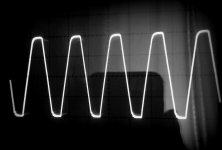
What's your input signal supposed to look like at 50kHz? Sine? Square? There's some ripple to be seen at the lower slope - is that due to clipping?
Your Hameg is very good . 1mv offset is extraordinary, It means first choice circuit to be paralleled. The dis symmetric saturation can be easily adjusted by biasing the inputs slightly higher than Vcc/2 , as it will end single supply. Now it can be good to listen the sound . Choose along your favorites the "Happy Together " of The Turtles (YouTube MP3) and hear the chorus refrain if it sounds good or distorted . You can by this decide definitely to go inverted or non inverted.
Last edited:
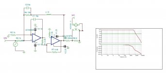
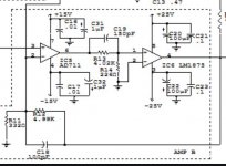
Here what may look like with inverted according to palstanturhin circuit but with AD826 . The distortion should be 2.5 times the distortion of AD826 in 2x gain . -100db 3rd .
Attachments
Last edited:
Hi guys
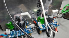
i do not want to disturb you 😉. as i want to show and try out by myself the parallel configuration with this LM1875 kit amp.
here it is
pic 1
this is just a paralleling the actual mono kit to build a 2x LM1875 into load of 4,459 R. ----i have to look for a lower resistor and more power it can be dissipate😀
all connection are under the PCB:
connect signal in
signal GND
power GND
output over the resistor 0,47R ---> then right to the load (4,459R)
i use just 0R47 5 Watt resistor what i thought thats ok for the first test
@27 Vsupply - DC offset measured at the speaker terminal with load connected is 3mV
pic 2
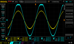
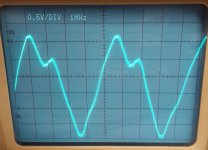
+/-20V supply at my Rigol PSU - input 510Vrms-10,8Vrms no clipping --> 26,15Watt- 2,42Amp into 4,459R
pic 3
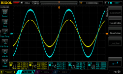
+/-25V supply at my Rigol PSU - input 640Vrms-13,6Vrms no clipping --> 41,48Watt- 3,05Amp into 4,459R
pic 4
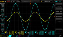
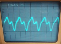
+/-27V supply at my Rigol PSU - input 680Vrms-14,5Vrms no clipping --> 47,5Watt - 3,25Amp into 4,459R
max power
pic 5
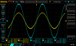
+/-27V supply at my Rigol PSU - input 760Vrms-15,9Vrms no clipping --> 56,7Watt - 3,565Amp into 4,459R
chris
i do not want to disturb you 😉. as i want to show and try out by myself the parallel configuration with this LM1875 kit amp.
here it is
pic 1
this is just a paralleling the actual mono kit to build a 2x LM1875 into load of 4,459 R. ----i have to look for a lower resistor and more power it can be dissipate😀
all connection are under the PCB:
connect signal in
signal GND
power GND
output over the resistor 0,47R ---> then right to the load (4,459R)
i use just 0R47 5 Watt resistor what i thought thats ok for the first test
@27 Vsupply - DC offset measured at the speaker terminal with load connected is 3mV
pic 2
+/-20V supply at my Rigol PSU - input 510Vrms-10,8Vrms no clipping --> 26,15Watt- 2,42Amp into 4,459R
pic 3
+/-25V supply at my Rigol PSU - input 640Vrms-13,6Vrms no clipping --> 41,48Watt- 3,05Amp into 4,459R
pic 4
+/-27V supply at my Rigol PSU - input 680Vrms-14,5Vrms no clipping --> 47,5Watt - 3,25Amp into 4,459R
max power
pic 5
+/-27V supply at my Rigol PSU - input 760Vrms-15,9Vrms no clipping --> 56,7Watt - 3,565Amp into 4,459R
chris
Attachments
-
 27 supply_input 760Vrms in_load R4,459_56,7Watt_max.png53.4 KB · Views: 162
 -
 27 supply_input 680Vrms in_load R4,459_47,5Watt.png52.1 KB · Views: 122
 -
 25 supply_input 640Vrms in_load R4,459_41,48Watt.png51.7 KB · Views: 129
 -
 20 supply_input 510Vrms in_load R4,459_26,1Watt.png51.1 KB · Views: 276
 -
 LM1875 parallel mode with 0R47.jpg158.5 KB · Views: 346
Last edited:
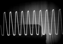
I have received my LM1875's today. The first one I tried was DOA; output was clinging to negative rail with some little oscillations visible, but no measurable short. The second one worked as expected, but unfortunately it seems to be only marginally stable with 6dB gain. The square wave response at 2Vpp into 8R shows some 40% overshoot, which is quite a bit too much I think. Adding 100nF to the output makes the square wave ring like a bell.
Next try will be to re-wire my prototype to the inverting configuration.
Next try will be to re-wire my prototype to the inverting configuration.
I have received my LM1875's today. The first one I tried was DOA; output was clinging to negative rail with some little oscillations visible, but no measurable short. The second one worked as expected, but unfortunately it seems to be only marginally stable with 6dB gain. The square wave response at 2Vpp into 8R shows some 40% overshoot, which is quite a bit too much I think. Adding 100nF to the output makes the square wave ring like a bell.
Next try will be to re-wire my prototype to the inverting configuration.
hi Preamp
can we see some scope pics?
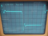
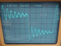
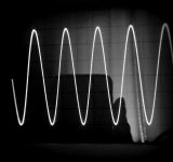
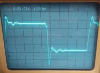
I had hoped to get around this, but here you are. 20kHz square wave at almost 2Vpp into 8R.
thx

Quickly tested the inverting version while I was at it. Used 1k at the inverting input and 2k as feedback resistor, with the non-inverting input tied to ground via a 10R resistor which was fetched from the scrap heap.
Doesn't look that good either. The ringing is damped much better now, but the spike on the negative slope is much more severe. What's more, this configuration has a huge power bandwidth up to and beyond 1MHz without any noticeable amplitude reduction, which might pose some problems...
Doesn't look that good either. The ringing is damped much better now, but the spike on the negative slope is much more severe. What's more, this configuration has a huge power bandwidth up to and beyond 1MHz without any noticeable amplitude reduction, which might pose some problems...
Attachments
Hi guys
..........................
pic 1
this is just a paralleling the actual mono kit to build a 2x LM1875 into load of 4,459 R. ----i have to look for a lower resistor and more power it can be dissipate😀
all connection are under the PCB:
connect signal in
signal GND
power GND
output over the resistor 0,47R ---> then right to the load (4,459R)
i use just 0R47 5 Watt resistor what i thought thats ok for the first test
@27 Vsupply - DC offset measured at the speaker terminal with load connected is 3mV
pic 2
+/-20V supply at my Rigol PSU - input 510Vrms-10,8Vrms no clipping --> 26,15Watt- 2,42Amp into 4,459R
pic 3
+/-25V supply at my Rigol PSU - input 640Vrms-13,6Vrms no clipping --> 41,48Watt- 3,05Amp into 4,459R
pic 4
+/-27V supply at my Rigol PSU - input 680Vrms-14,5Vrms no clipping --> 47,5Watt - 3,25Amp into 4,459R
max power
pic 5
+/-27V supply at my Rigol PSU - input 760Vrms-15,9Vrms no clipping --> 56,7Watt - 3,565Amp into 4,459R
chris
Good work, Chris. You are in the lead.
56W in 4 Ohm (close to) means 110W in 8 Ohm with a BTL version. When you can handle the current, bridging is rather trivial. Parallel configuration of two chips doubles the current handling but quadruples the power capability. This is why paralleling is a good trick to master when you want high output levels
Also I have the problem that my power resistor gets really hot in no time.
Quickly tested the inverting version while I was at it. Used 1k at the inverting input and 2k as feedback resistor, with the non-inverting input tied to ground via a 10R resistor which was fetched from the scrap heap.
Doesn't look that good either. The ringing is damped much better now, but the spike on the negative slope is much more severe. What's more, this configuration has a huge power bandwidth up to and beyond 1MHz without any noticeable amplitude reduction, which might pose some problems...
True, not a very pretty sight. You seem to be very much on top in general so you have: 1) Very short leads on your power rail decoupling? 2) 100nF HF decoupling of the power rails? 3) Very short leads on your feedback resistor? 4) Short leads on your Zobel-network?
LM1875 is not very forgiving when the leads are not short.
Could we eventually have a photo of the LM1875 chip you use?
I have received my LM1875's today. The first one I tried was DOA; output was clinging to negative rail with some little oscillations visible, but no measurable short. The second one worked as expected, but unfortunately it seems to be only marginally stable with 6dB gain. The square wave response at 2Vpp into 8R shows some 40% overshoot, which is quite a bit too much I think. Adding 100nF to the output makes the square wave ring like a bell.
Next try will be to re-wire my prototype to the inverting configuration.
Can you please decrease the feedback resistors to be 180 ohm 1W/100 ohm in non inverting.
FF , to cool your load , apply two resistors of 5W in series in U shape and plunge them in a small cup of water .
Last edited:
I found this Semiconductor Datasheets: 33W Bridge Composite Amplifier . The first composite amplifier published in a magazine was using LM1875 . If someone can recall it where please inform.
Attachments
Member
Joined 2006
I found this Semiconductor Datasheets: 33W Bridge Composite Amplifier . The first composite amplifier published in a magazine was using LM1875 . If someone can recall it where please inform.
This?
https://ia601701.us.archive.org/15/...s_1992-11/Radio_Electronics_November_1992.pdf
- Home
- Amplifiers
- Chip Amps
- LM1875 in parallel configuration and used in a composite amplifier.