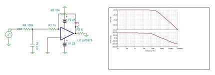
This circuit can lower the gain with flat response (...)
But only down to 20dB, or else the amp will become unstable or only marginally stable.
In my circuit I have added an input lowpass filter to counter the rising gain at higher frequencies to get back to an overall flat frequency response.
I don't quite get your second option. What does L1 with a value of 0H do?
Have another look to the graph. The gain is 0db. Here is another with -20db. Note that the frequency response remains the same.But only down to 20dB, or else the amp will become unstable or only marginally stable
If you adjust L1 to 1G Henry, you get the open loop response.
Attachments
Last edited:
Have another look to the graph. The gain is 0db.
You're right of course. Didn't notice the inverting configuration. I'll try that one with my TDA2030A prototype.
If you adjust L1 to 1G Henry, you get the open loop response.
Simulator stuff then. Hard to separate from the "real" parts if you didn't create the schematic yourself 🙁
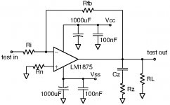
I prepared this test circuit today. It will be used to test stability of LM1875 with audio-band gain significantly below 20dB. Inverting and non-inverting configurations will be tested. If stable, a square-wave signal will be used at the input to give a qualitative impression of the stability margin.
Very short feedback resistor leads. Short Zobel network leads and power decoupling capacitor leads. Huge heatsink.
First test (hopefully tomorrow):
Inverting coupling. Vcc=+18V. Vss=-18V. RL=10R/5W. Cz=220nF foil. Rz=1R film. Rfb=4K7. Ri=2K2. Rn=1K.
Very short feedback resistor leads. Short Zobel network leads and power decoupling capacitor leads. Huge heatsink.
First test (hopefully tomorrow):
Inverting coupling. Vcc=+18V. Vss=-18V. RL=10R/5W. Cz=220nF foil. Rz=1R film. Rfb=4K7. Ri=2K2. Rn=1K.
Attachments
Last edited:
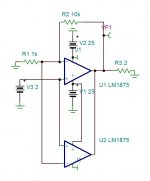
unlike 3886 the 1875 doesn't have internal feedback and the output stage is floating between current mirrors. By this it is very probably a trans Conductance amplifier with high impedance current outputs . If it is the case then bingo, we only need to parallel the 1875s foot to foot in parallel. To test the eventually the circuit bellow can show . If the output gets to 16V then both ICs are working together limiting each 4A.
Attachments
AMAZING! I just did a first quick test of the circuit shown in posting #64 (inverting configuration, gain just above 2 times). No signs of instability with shorted input. With my function generator (50 Ohm output), I could take the amplifier to clipping at +/- 15V (1KHz) without any instability signs. A square wave input showed a rather perfect square-wave (0.5ms time base) at the output all the way to +/-15V, again without signs of instability. A good start!
Thanks to kokoriantz and palstanturhin for letting me know that the datasheets are not always the absolute law.
Thanks to kokoriantz and palstanturhin for letting me know that the datasheets are not always the absolute law.
Now put 100nF in parallel to the load resistor and look for some ringing at the rising edges of the square wave output.
Can you try non inverting with 2k/1K and 200/100 ohm to see how it effects the frequency response.
unlike 3886 the 1875 doesn't have internal feedback and the output stage is floating between current mirrors. By this it is very probably a trans Conductance amplifier with high impedance current outputs . If it is the case then bingo, we only need to parallel the 1875s foot to foot in parallel. To test the eventually the circuit bellow can show . If the output gets to 16V then both ICs are working together limiting each 4A.
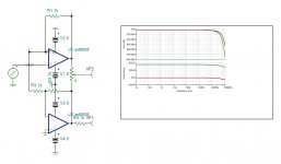
An interesting idea. We could either make more LM1875 "slaves" of a single feedback-loop so they behave alike, or we could simply turn each LM1875 into a separate trans-conductance amplifier (such as shown by Mr. Joe Rasmussen) and add the output currents. Currents can be added in parallel and even slight differences in current levels are no problem.
One general problem I have noticed from modular parallel power supplies is evidently load sharing but also cross regulation. Amplifiers are in principle sophisticated precision power supplies so I guess the same concerns apply for power amplifiers. If a high gain amplifying circuit without own feedback loop is put in parallel with a similar high gain amplifier, they will respond differently to the same feedback signal. Then, they will not share the load well.
If two high gain amplifier circuits with individual feedback loops are put in simple parallel, they have the same feedback signal. So when one amplifier controlled by its own feedback loop changes its contribution to a common output, the signal feed back to the other amplifier changes and makes that amplifier react by changing its contribution to the common output which again makes the first amplifier react etc.....
Converting the contributions of more parallel power supplies into a sum of individual current contributions is a known structure. Then a single feed-back voltage signal, taken from the load, is used to control the level of output current from each power supply and the current summing is unproblematic.
A number of "trans-amp" circuits could be connected in parallel and the common output be feed-back to the composite amplifier OP-AMP for that OP-AMP to control the current contribution level of the parallel trans-amp modules.
Indeed an interesting idea.
Last edited:
Can you try non inverting with 2k/1K and 200/100 ohm to see how it effects the frequency response.
I will try. The reason for me to choose 2K2 as input impedance for one LM1875 block is that with three blocks in parallel, the effective input impedance is just above the 600 Ohm high quality OP-AMPs can drive. If I use a very low input impedance, I will need a buffer as well.
Now put 100nF in parallel to the load resistor and look for some ringing at the rising edges of the square wave output.
Will try this afternoon.
If you make it function non inverting , you can parallel as many as you want.I will try. The reason for me to choose 2K2 as input impedance for one LM1875 block is that with three blocks in parallel, the effective input impedance is just above the 600 Ohm high quality OP-AMPs can drive. If I use a very low input impedance, I will need a buffer as well.
By paralleling pin to pin if it works , ok the trans Conductances will not be all identical but for such low cost and simple circuit a forth pair can be added.
Now put 100nF in parallel to the load resistor and look for some ringing at the rising edges of the square wave output.
I did. Honestly, I also inserted 0.47R (which I intend for load balancing) in-between the chip output and the load resistor. With 100nF (polypropylene) across the load resistor, I have very little ringing at the output of the chip.
100nF directly at the output of an amplifier will always create ringing I believe, but in this case it would be unrealistic.
If you make it function non inverting , you can parallel as many as you want.
By paralleling pin to pin if it works , ok the trans Conductances will not be all identical but for such low cost and simple circuit a forth pair can be added.
You are right as such but I ran into another problem when checking band-with. Just below 100Khz, the amplitude limits start reducing and above 100Khz the sine-wave starts looking triangular. Like if I have a slew-rate problem. I reduced all three resistors Rfb, Ri and Rn to below 1/10th to see if that helped significantly. I was close to the values you suggest. However, reducing the impedance level did not help much.
Are you aware of any slew-rate issues for LM1875?
The document says 70khz . LM3886 is also 100khz for full excursion. Is the test inverted or non inverted ?You are right as such but I ran into another problem when checking band-with. Just below 100Khz, the amplitude limits start reducing and above 100Khz the sine-wave starts looking triangular. Like if I have a slew-rate problem. I reduced all three resistors Rfb, Ri and Rn to below 1/10th to see if that helped significantly. I was close to the values you suggest. However, reducing the impedance level did not help much.
Are you aware of any slew-rate issues for LM1875?
The document says 70khz . LM3886 is also 100khz for full excursion. Is the test inverted or non inverted ?
Until now I have only tried the inverted configuration. I wanted to test that well to see if there were any stability problems but I found none. I also experimented a little with the Zobel network. The best combination I found was with 100pF across Rfb and Cz reduced to 100nF. Tomorrow I will go on and try the non-inverting configuration as well.
I tried the very low values for Rfb and Ri but noticed no advantages compared to the values initially proposed.
You mention a document informing us that full output voltage excursion is no longer possible above 70Khz. I looked for such information but did not see it in the datasheet. The 70Khz fits well with my observations.
Many thanks for the help.
I prepared this test circuit today. It will be used to test stability of LM1875 with audio-band gain significantly below 20dB. Inverting and non-inverting configurations will be tested. If stable, a square-wave signal will be used at the input to give a qualitative impression of the stability margin.
Very short feedback resistor leads. Short Zobel network leads and power decoupling capacitor leads. Huge heatsink.
First test (hopefully tomorrow):
Inverting coupling. Vcc=+18V. Vss=-18V. RL=10R/5W. Cz=220nF foil. Rz=1R film. Rfb=4K7. Ri=2K2. Rn=1K.
Awesome! I've been looking for a cheap, reasonable-sounding low gain amp for ages ... and inverted makes the performance better!

I recall that the + and - inputs want to see the same resistance (and parallel capacitance) for the best balance and improved performance.
So the negative input will see Ri (2.2k) in series with the output impedance of the previous stage (usually ~100R), so 2.3k. That's in parallel with Rfb (4.7k) so 2.3k||4.7k=1.54k
Thus Rn should be 1.54k too (1% resistors or 5% measured).
I'm not sure how to calc the equivalent parallel capacitance but hopefully someone will chime in.
Another option would be to use a 2k multi turn trim pot to dial in the lowest offset (DMM) or offset and distortion (balance) if you have the test equipment. (And once the resistance is perfectly dialed in, you could do the same thing with the capacitance and a close range of caps--if you have the test equipment!)
Cheers,
Jeff
PS Does this circuit work with the LM3886/LM3887 or one of the other good chip amps? The extra power (if needed) would make this superb!

PPS Putting a decent buffer on the input will isolate (better performance) it from the previous stage.
Last edited:
I use LM3886 only with a gain of 2.8. It needs 180/100 ohms feedbacks in non inverting mode. For the voltage gain ,I use 600:10k good quality (24$ a pair) transformer. I see on YouTube Live distortion measured of LM1875 0.011% most probably with gain of application circuit 26db. If running at gain of 6db you have an extra zero in the above number.Awesome! I've been looking for a cheap, reasonable-sounding low gain amp for ages ... and inverted makes the performance better!
I recall that the + and - inputs want to see the same resistance (and parallel capacitance) for the best balance and improved performance.
So the negative input will see Ri (2.2k) in series with the output impedance of the previous stage (usually ~100R), so 2.3k. That's in parallel with Rfb (4.7k) so 2.3k||4.7k=1.54k
Thus Rn should be 1.54k too (1% resistors or 5% measured).
I'm not sure how to calc the equivalent parallel capacitance but hopefully someone will chime in.
Another option would be to use a 2k multi turn trim pot to dial in the lowest offset (DMM) or offset and distortion (balance) if you have the test equipment. (And once the resistance is perfectly dialed in, you could do the same thing with the capacitance and a close range of caps--if you have the test equipment!)
Cheers,
Jeff
PS Does this circuit work with the LM3886/LM3887 or one of the other good chip amps? The extra power (if needed) would make this superb!
PPS Putting a decent buffer on the input will isolate (better performance) it from the previous stage.
Last edited:
- Home
- Amplifiers
- Chip Amps
- LM1875 in parallel configuration and used in a composite amplifier.