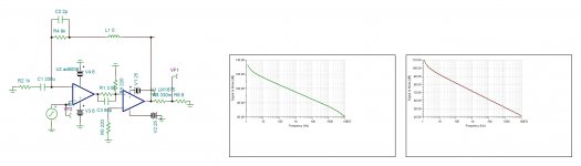
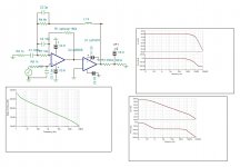
palstanturhin , you were right to ask noise simulation. Indeed LM1875 is rather noisy . But by the original composite circuit adapter for AD8008 , it falls 20db . I suppose the Dtot also decreases by the same ratio. I posted bellow the comparative simulation . My precedent "second option " have 10db higher noise for identical transient response. So we forget all and restart with a proven version.
Attachments
Good work, Chris. You are in the lead.
56W in 4 Ohm (close to) means 110W in 8 Ohm with a BTL version. When you can handle the current, bridging is rather trivial. Parallel configuration of two chips doubles the current handling but quadruples the power capability. This is why paralleling is a good trick to master when you want high output levels
Also I have the problem that my power resistor gets really hot in no time.
Yes the 2 chip parallel is not really difficult - two weak points i have:
the 0R47 resistor is to high --> 0R1 - i could have more output power,
still this high power oscillation. at the one board i have everything original but the 3R3 resistor at the Zobel - is that the trick? i measured the inductance af all my version of resistor here 1W or 3W 1R - or this 1W 3R3 - no really huge different.
chris
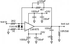
I found this Semiconductor Datasheets: 33W Bridge Composite Amplifier . The first composite amplifier published in a magazine was using LM1875 . If someone can recall it where please inform.
Many thanks to kokoriantz and CFT for this excellent article. Excellent because it in a qualitative way (without drowning us in mathematics) explains the problems and solutions when designing a composite amplifier: characteristics of the power amp element, choice of the controlling OP-AMP, parallel coupling of power amp elements, use of a DC offset compensating circuit etc.
I can only recommend anybody wanting to know more about (ultra) low THD composite amplifiers to read this article (pages 38-44) twice.
Also many thanks to kokoriantz for the original but very efficient idea of simply submerging my hot load-resistor in water. With such low resistance values and moderate voltage levels it should work. It may leave some corrosion long term as water combined with electrical voltages/currents is known to do.
For those less skilled with electrical circuits, NEVER COMBINE HIGHER VOLTAGES WITH WATER AS YOU MAY EASILY GET SEVERE ELECTRICAL SHOCKS!!
Yes the 2 chip parallel is not really difficult - two weak points i have:
the 0R47 resistor is to high --> 0R1 - i could have more output power,
still this high power oscillation. at the one board i have everything original but the 3R3 resistor at the Zobel - is that the trick? i measured the inductance af all my version of resistor here 1W or 3W 1R - or this 1W 3R3 - no really huge different.
chris
Hi Chris,
The load balancing resistor value is a trade-off between power losses in the resistors, the static (DC voltage offset) as well as dynamic (difference in gain) variation in output voltage of each power amplifier element (voltage source) and the load-imbalance or cross currents you will allow. Just as a figure, I would not allow more than 100mA.
The signs of fine oscillation on peaks of your sine-wave, you may reduce with your 100pF (or a bit more) across the feedback resistor. Your Zobel-network should be with 1 Ohm damping but the capacitor can eventually be lowered to 100nF.
LM1875 has this tendency of oscillation with high input voltages and high output currents. This is why I prefer using three 1875 in parallel to give each LM1875 more current margin. You may also try lowering the supply voltage (which evidently also reduces the load current).
If you make the load with two resistors of 5W 3.9 ohm in series ,bent in U shape , the +/- electrodes do not touch the water . If you apply high power the water boils but the temperature remains constant 100°C with resistive value slightly higher.
Hi Chris,
The load balancing resistor value is a trade-off between power losses in the resistors, the static (DC voltage offset) as well as dynamic (difference in gain) variation in output voltage of each power amplifier element (voltage source) and the load-imbalance or cross currents you will allow. Just as a figure, I would not allow more than 100mA.
The signs of fine oscillation on peaks of your sine-wave, you may reduce with your 100pF (or a bit more) across the feedback resistor. Your Zobel-network should be with 1 Ohm damping but the capacitor can eventually be lowered to 100nF.
LM1875 has this tendency of oscillation with high input voltages and high output currents. This is why I prefer using three 1875 in parallel to give each LM1875 more current margin. You may also try lowering the supply voltage (which evidently also reduces the load current).
Thank you again for the clear words.
i do not want to disturb your composite ideas - so - i guess with "just" parallel power chip this ebay kit i will write in the other thread.
hopefully i have time for the composite in the Christmas holidays 🙂
chris
1) Very short leads on your power rail decoupling? 2) 100nF HF decoupling of the power rails? 3) Very short leads on your feedback resistor? 4) Short leads on your Zobel-network?
LM1875 is not very forgiving when the leads are not short.
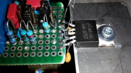
Could we eventually have a photo of the LM1875 chip you use?
1) Yes
2) Yes
3) No
4) Yes
I'll try to make the resistor leads as short as possible. That's not so easy, because I'm using a piece of plated-through perfboard that makes desoldering a PITA really. Will make a picture when I'm back home.
Can you please decrease the feedback resistors to be 180 ohm 1W/100 ohm in non inverting.
Will do.
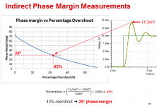
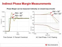
Found some nice graphs regarding phase margin and percent overshoot:
Attachments

simplified and re adjusted of the preceding version. The noise is measured R1 . The frequency response is limited to 100khz to avoid slew rate mismatch problem. All now is needed to know how to parallel. If it is paralleled pin to pin , then the one with higher gain will pull more than the others . Thanks to FF's observation that at high power the 1875 oscillates , it means the Hfe of the outputs at high currents decrease, by this the other ones deliver more . This is the same phenomena as a carriage pulped by several horses . If one is more energetic than the others , it will pull the carriage alone but it will get quickly tiered, easing himself to let the other pull as much . All need to know what is the output impedance of LM1875 without feedback. The simulator gives a constant 0.1 ohm but it is not realistic.
Attachments

Power dissipation . Each amp drains 100ma at quiescent says the datasheet. With 50V supply, it dissipates 5W . But , on figure 9 ,4ohm and figure 10, 8 ohm it shows 10W and 8W dissipating. Can someone explain? If we consider 5W , then 4,pairs of it needs to dissipate 40W . With my experience with class A amps a heat sink of 8 inchs wide 4 inches high with about 4cm thick , at 30°C ambient rises to52°C . The good news is that the power dissipation remains near constant with power if each amp gets the load 16 ohms with 50V supply.
Sorry for suddenly dropping out of the discussion yesterday. My wife slipped in the garden yesterday and broke her arm so we had to wait the day for surgery at the hospital. From today, I am the main service provider at home with two functional hands so I will have less time for DIY the next couple of weeks. By the way, a Merry Christmas and a happy New Year to everyone.
For the design shown in the excellent article about composite amplifiers, I have two doubts.
The use of LM1875 without local feedback for each LM1875 leaves, in my view, a transfer function inside the loop that is not fully reliable gain-wise. My personal perception is that with feedback on each LM1875 chip, a predictable gain and stability behavior can be obtained and the operational conditions for the loop controlling OP-AMP, when turned into a composite amplifier, ensured. The article uses a down-throttled version of the raw LM1875 gain. I guess, with considerable initial spread and significant temperature dependence as the result. I could also imagine TIM distortion (Transient Intermodulation Distortion) issues like in the days where the amplifiers were designed with very high untamed open-loop gain. Admitted, I have never tested the transfer function of the LM1875 in such a coupling and it could be useful for me to do so. My expectation is that it will be difficult to assure the OP-AMP operates in an area with low THD due to the pretty high and variable raw gain of the LM1875.
The second issue is the number of AD711 used. I guess that only the number of parallel LM1875 needed to give the necessary current capability and a single OP-AMP are really needed.
Last edited:
Sorry for suddenly dropping out of the discussion yesterday. My wife slipped in the garden yesterday and broke her arm so we had to wait the day for surgery at the hospital. From today, I am the main service provider at home with two functional hands so I will have less time for DIY the next couple of weeks. By the way, a Merry Christmas and a happy New Year to everyone.
.
HI FF
sorry to hear that with your wife. keep her and yourself comfortable as good as possible the next weeks. health is more important then the amp 🙂
chris
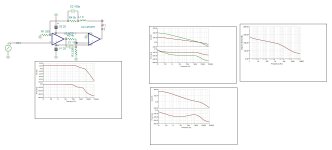
Here is the sim of the article circuit. The upper right is the open loop response of ad711 and 711+1875 without intermediate network , notice 180° phase shift above 1kHz. Bellow right is with network. Left, in closed loop . Compare it with mine .
Attachments
Last edited:
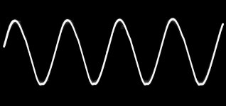
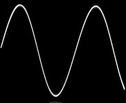
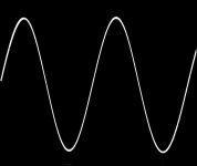
Before moving on with modification of my LM1875 breadboard to test the LM1875 configuration in the composite amplifier article, I decided to document some last results of the LM1875 with inverting coupling and a gain just above 2 times.
Output curves:
1KHz - 36Vpp sine-wave (a bit below clipping at +/-20V)
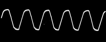
1KHz - 30Vpp square-wave
8KHz - 36Vpp sine-wave (a bit below clipping at +/-20V)
8KHz - 30Vpp square-wave
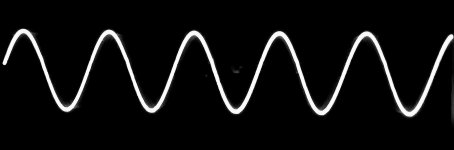
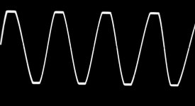
20KHz - 36Vpp sine-wave (a bit below clipping at +/-20V)
20KHz - 30Vpp square-wave
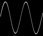
100KHz - 10Vpp sine-wave (output amplitude limited by the slew-rate)
100KHz - 10Vpp square-wave (output amplitude limited by the slew-rate)
200KHz - 6Vpp sine-wave (output amplitude limited by the slew-rate)
Output curves:
1KHz - 36Vpp sine-wave (a bit below clipping at +/-20V)
1KHz - 30Vpp square-wave
8KHz - 36Vpp sine-wave (a bit below clipping at +/-20V)
8KHz - 30Vpp square-wave
20KHz - 36Vpp sine-wave (a bit below clipping at +/-20V)
20KHz - 30Vpp square-wave
100KHz - 10Vpp sine-wave (output amplitude limited by the slew-rate)
100KHz - 10Vpp square-wave (output amplitude limited by the slew-rate)
200KHz - 6Vpp sine-wave (output amplitude limited by the slew-rate)
Attachments
-
 LM1875Test2.jpg44.8 KB · Views: 422
 -
 LM1875_200KHz6VppSine.jpg159.9 KB · Views: 124
 -
 LM1875_100KHz10VppSquare.jpg200.8 KB · Views: 90
 -
 LM1875_100KHz10VppSine.jpg160 KB · Views: 92
 -
 LM1875_20KHz30VppSquare.jpg175.2 KB · Views: 98
 -
 LM1875_20KHz36VppSine.jpg254 KB · Views: 80
 -
 LM1875_8KHz30VppSquare.jpg194.2 KB · Views: 114
 -
 LM1875_8KHz36VppSine.jpg184.1 KB · Views: 101
 -
 LM1875_1KHz30VppSquare.jpg596.8 KB · Views: 353
 -
 LM1875_1KHz36VppSine.jpg230.5 KB · Views: 403
Last edited:
That's looking really nice, much better than my results! Adding some pF across the feedback resistor just made things worse. Makes me think that my LM1875 are anything but genuine... or that my prototype is sufficiently insufficient 😱.
The non-inverting version with lowered resistor values (100/180) is pretty much the same.
EDIT: Here's another thread with a familiar looking circuit in the first post: Composite LM1875 stability issues
The non-inverting version with lowered resistor values (100/180) is pretty much the same.
EDIT: Here's another thread with a familiar looking circuit in the first post: Composite LM1875 stability issues
Last edited:
Faux:
Could you do clipping tests also, just to see what happens.
That may be of interest when deciding which stage should clip first, the 1875 or the opamp?
Could you do clipping tests also, just to see what happens.
That may be of interest when deciding which stage should clip first, the 1875 or the opamp?
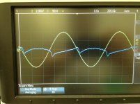
FF, can you apply a pot. From input to output and adjust for null to see the shape of the distortion for 1 kHz 1W. Joyeux Noël.
Last edited:
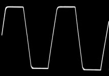
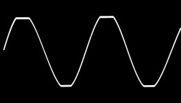
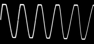
The easiest first - clipping wave-forms. Done at 1KHz, 10KHz and 20KHz. For all, clipping at +/-20V (40Vpp). 10KHz photo not very sharp.
For the time being I only have an LM1875 on test, no OP-AMP. So, it is obviously the LM1875 that "clips". This is why I want well controlled fixed gain in the power amplifier such that I know the amplitude range of the OP-AMP during operation (no OP-AMP clipping).
According to what I paid, mine should also not be "genuine". But mine is sufficiently sufficient to show about how a sufficiently genuine LM1875 behaves. I just checked my generous stock of LM1875. Lasse, if you send me a "PM" with a mail address where you can pick up a letter, I will mail you two hopefully better items and you are back in the game. Nobody in Europe will do serious work before in January. The mail system may work if we avoid strike in LaPoste this year.
Kokoriantz, I had to read your request twice to understand your aim. Am I right in that you wish to subtract the output signal from the input signal such that you (ideally) can see the distortion component? Be aware that my signal generator is an "Instek" with a THD of 0.1%. I guess that even 0.1% may tell you something about which harmonics are dominating? I do unfortunately not have a spectrum analyzer but if I use my Hameg with the input signal on one channel and the output signal on the other channel, subtract the two channels and adjust the sensitivity of the two channels for a minimum output signal, will that do?
Bonnes fêtes.
Attachments
Last edited:
Lasse, if you send me a "PM" with a mail address where you can pick up a letter, I will mail you two hopefully better items and you are back in the game.
Sounds like a plan. One piece might be enough though, only for testing and as a sanity check. In return I can send you one of my parts, so we can double-check. I'll add a picture postcard from Monkey Island then 😛!
Frohe Weihnachten!
You see like this . As the NFB now is 10 times higher than the model used for datasheet measurements, yes you already added an extra zero to the distortion number, but the crossover distortion compensation can be limited from now on by the slew rate . The scope will show you.
Attachments
Last edited:
- Home
- Amplifiers
- Chip Amps
- LM1875 in parallel configuration and used in a composite amplifier.