It's the blind leading the blind a bit... But if I was way off I'm sure someone would have interjected by now [emoji23]
1 3A slow for mains -Yep
2 2.5A fast between toroid 18vAC and rectifier boardThis is what I do but SLOW (T) type fuses as capacitors charging can pop them sometimes otherwise
3 2.5A fast 18vDC to amplifiers Personally I dont bother with this as its already inherently looked after by 2 above....
4 250mA fast between 18vAC transformer and the circuit protection PCB (guessing this one at the moment as no current details provided by seller, but I can test draw on bench) yep make sure its rated OK for
Do I need to test DC offset at the speaker outputs? There is no bias adjustment (all taken care of in the IC I am told).
Yes it is but normal rules apply to keep it to a minimum. Try to make feedback and input to 0V resistors same value to minimise the effects of current flowing in both.
I had to turn the IEC socket over (fuse holder at bottom), is this illegal?
Not sure but does fuse now fall out when drawer is open?
I am not going to use an inrush current limiting NTC thermister before the toroid.
There is not much need to on smaller toroids. If it dims your lights it should however be considered!
I will secure all connections and stabilize the big caps with hot snot
XD lovely!!
...But in the event of a short it should blow anyway before anything catches fire too much, which is the main thing [emoji106]
Hi Dunk02, on the topic of things catching fire, I don't want to unnecessarily worry you, but if you're using the generic ebay kit and components, don't be surprised if some of your resistors burn up within the first few weeks (I've had issues with the 10ohm resistor and from what I gather other people have had similar problems). It's easy to buy replacements and resolder them - so its not a major issue. But seeing that you are going to the effort, and the boards only cost a few dollars, you may want to consider ordering some extra boards with the view to building them with known components at a later time. Once you've got the amp built, it is easy to swap the boards over and it just gives you that extra peace of mind that the amp will last longer.
1 3A slow for mains -Yep
2 2.5A fast between toroid 18vAC and rectifier boardThis is what I do but SLOW (T) type fuses as capacitors charging can pop them sometimes otherwise
3 2.5A fast 18vDC to amplifiers Personally I dont bother with this as its already inherently looked after by 2 above....
4 250mA fast between 18vAC transformer and the circuit protection PCB (guessing this one at the moment as no current details provided by seller, but I can test draw on bench) yep make sure its rated OK for
Do I need to test DC offset at the speaker outputs? There is no bias adjustment (all taken care of in the IC I am told).
Yes it is but normal rules apply to keep it to a minimum. Try to make feedback and input to 0V resistors same value to minimise the effects of current flowing in both.
I had to turn the IEC socket over (fuse holder at bottom), is this illegal?
Not sure but does fuse now fall out when drawer is open?
I am not going to use an inrush current limiting NTC thermister before the toroid.
There is not much need to on smaller toroids. If it dims your lights it should however be considered!
I will secure all connections and stabilize the big caps with hot snot
XD lovely!!
Thanks for the feedback and confirmations. You might save me a bit of work.
Hi Dunk02, on the topic of things catching fire, I don't want to unnecessarily worry you, but if you're using the generic ebay kit and components, don't be surprised if some of your resistors burn up within the first few weeks (I've had issues with the 10ohm resistor and from what I gather other people have had similar problems). It's easy to buy replacements and resolder them - so its not a major issue. But seeing that you are going to the effort, and the boards only cost a few dollars, you may want to consider ordering some extra boards with the view to building them with known components at a later time. Once you've got the amp built, it is easy to swap the boards over and it just gives you that extra peace of mind that the amp will last longer.
Ok good point and thanks. I already replaced the electrolytics with Panasonics from a RS Components. Maybe I should get some quality resisters and do a swap now. Want it to be durable but am not expecting to run it anywhere near full power.
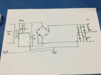
“I will put a 10nf 300v Kemet X1 cap across the mains switch to eliminate any on/off noise, even though I don’t know if it is necessary”
I think this now needs to go after the switch, across the transformer primary active and neutral.
I think this now needs to go after the switch, across the transformer primary active and neutral.
Excuse the question. I use this kit like headphones amp (with B +/- 18Vdc) and it works very well, but I wonder if it would not be necessary to add a coupling cap on the output.
Edit: offset is 0Vdc.
Edit: offset is 0Vdc.
“I will put a 10nf 300v Kemet X1 cap across the mains switch to eliminate any on/off noise, even though I don’t know if it is necessary”
I think this now needs to go after the switch, across the transformer primary active and neutral.
forgot to add that to my own list but you've discovered it now...

My LM1875 "Gainclone" monoblock…
Built in 2000 before I even realised people were building these for serious listening; I made a couple for "laboratory Amplification" rearranging input circuits so they were bootstrapped giving a higher inpout impedance. This was useful for testing valve preamps with....
Built in 2000 before I even realised people were building these for serious listening; I made a couple for "laboratory Amplification" rearranging input circuits so they were bootstrapped giving a higher inpout impedance. This was useful for testing valve preamps with....
Last edited:
Hi Guys
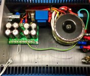
Back from holidays and some home renovations. Started assembly.
Retapped the chassis screw holes and assembled using stainless star washers. Sanded a patch between the front plate and side plate (star washers would not fit). Chassis now fully earthed.
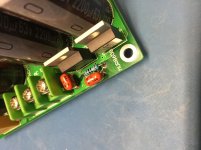
Problem: on the power supply board, a 10R resistor connects to a track that get earthed to the chassis when screwed down; this keeps blowing. The input voltage to the board is about 21v AC from the 18v transformer. When the screw is isolated from ground there are no issues and the output voltage is +/0/- 29v DC? What could be going on here?
Thanks
Back from holidays and some home renovations. Started assembly.
Retapped the chassis screw holes and assembled using stainless star washers. Sanded a patch between the front plate and side plate (star washers would not fit). Chassis now fully earthed.
Problem: on the power supply board, a 10R resistor connects to a track that get earthed to the chassis when screwed down; this keeps blowing. The input voltage to the board is about 21v AC from the 18v transformer. When the screw is isolated from ground there are no issues and the output voltage is +/0/- 29v DC? What could be going on here?
Thanks
Attachments
Last edited:
Is the resister and its connected capacitor providing a route to ground for any DC on the input? In which case has the cap shorted and is letting high AC current to leak to ground?
PS no connections made from the ouput terminals in the above desciption ( forgot to mention)
Another Q, does the 10nf X1 cap across the 240v switch naturally leak current? Even with the power switch off I measure a 1 volt AC between te terminal of the secondary windings on the small potted transformer.
Thanks
Anyone?
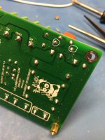
I think the reverse engineered diagram might have errors but I measured >50v between the “hot screw hole” and the chassis earth when the board has power but no load.
I think the reverse engineered diagram might have errors but I measured >50v between the “hot screw hole” and the chassis earth when the board has power but no load.
you have a short from your chip tab to the chassis.....
No amplifiers boards connected yet!
More troubleshooting over on the PS forum.
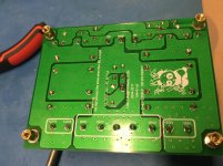
Power supply issue now sorted out with help from the Power Supplies Forum.
There was a short between an earthed mounting washer and the positive DC rail that was detected with a 100V insulation tester (nice spark!). The PS (8800uF per rail) was tested at 25V and delivered 2.5 A into an electronic dummy load with about 1.8V P-P ripple.
Next I will check the speaker protection board.
In the meantime I have replaced all the resistors and some of the capacitors on the LM1875 boards with branded parts (Panasonic caps and Dale resistors) so I need to do some bench testing before assembling it all together.
Attachments
Last edited:
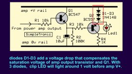
I always wanted to add a clipping indicator but couldn’t find a circuit until now.
Does anyone see any issues making a small to take two of these circuits, one for each channel?
Also, are there flush mount light pipe LED holders available for a nice install without a bezel on the front panel (8mm thick)? I think I use this method for the power indicator LED.
Does anyone see any issues making a small to take two of these circuits, one for each channel?
Also, are there flush mount light pipe LED holders available for a nice install without a bezel on the front panel (8mm thick)? I think I use this method for the power indicator LED.
Attachments
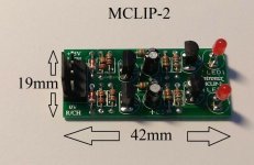
Also found:
>this PCB on EasyDA but there is no description. 10 JLCPCB boards for $7 shipped. Opamp based circuit
> and another 2 channel kit on eBay at about $20
Both are quite small but I think I need two boards for the first one.
>this PCB on EasyDA but there is no description. 10 JLCPCB boards for $7 shipped. Opamp based circuit
> and another 2 channel kit on eBay at about $20
Both are quite small but I think I need two boards for the first one.
Attachments
- Home
- Amplifiers
- Chip Amps
- LM1875 Amp layout