my vu meter circuit is slightly different. I have resistor from pin 7 connected to pin 8 and pin number 8 goes to variable resistor instead of the ground. isnt that right?
Tryed your circuit works same.. 😀 still 6 leds 😀 Wow i didint thought that could be so hard.... took me 2 months and i still cant build that freaking 10 led vu meter.
my vu meter circuit is slightly different. I have resistor from pin 7 connected to pin 8 and pin number 8 goes to variable resistor instead of the ground. isnt that right?
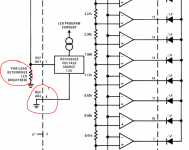
That set up doesn't give the highest sensitivity. Try it like this. I also read something else in the data sheet... which we can worry about that later, and that is that the supply voltage to the LED's should be limited to 7 volts to avoid overheating the IC with to high a loading.
Attachments
in the second photo. Shouldnt the middle leg of the variable resistor be connected with side one?
Oh and i noticed one more thing. When i tried to disable connection between the variable resistor middle leg and the side one all the leds blink!!!!! Scheme seems working but the leds blink very unbrigthly i can barely see them🙂 and when i connect variable middle leg to side one 6 leds blink but very bright and nice
in the second photo. Shouldnt the middle leg of the variable resistor be connected with side one?
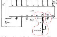
It can be wired like that but that is lowering the sensitivity. The data sheet suggests that wiring pin 8 direct to ground gives the highest sensitivity (so all the LED's light up for just 1.25 volts applied to input). Pin 6 and 7 connect together and these go via a resistor to ground. The value of this resistor sets the brightness.
Oh and i noticed one more thing. When i tried to disable connection between the variable resistor middle leg and the side one all the leds blink!!!!! Scheme seems working but the leds blink very unbrigthly i can barely see them🙂 and when i connect variable middle leg to side one 6 leds blink but very bright and nice
Wire it up as shown in the first picture and with pins 6 and 7 joined.
i dont quite understand those connections in the first photo. 8 is connected to the ground? and 7 connects one side variable resistor?
i think i wired it up. I can see that without additional resistor to pin 7 leds blink alot less brighter and still 6-7 leds ;/
maybe should i do everything without opamp? because i have built opamp and vu meter on the same breadbouard and should i try connecting my vumeter with opamp or run just a single vu meter?
i had keep changing everything and it stopped working at all... can someone send me really good working 10 led vu meter lm3915 circuit which could i do ??
the Lm 3915 you have is a good 10 led vu meter it's used widely in many commercial products without a problem.
i dont quite understand those connections in the first photo. 8 is connected to the ground? and 7 connects one side variable resistor?
Yes, pin 8 to ground. Don't go to low in value with the variable resistor, particularly if there is no series resistor added. Otherwise you might overload the chip. Just make it 5k as a safe value. Doesn't matter if the LED's are dim... get kit working first.
i think i wired it up. I can see that without additional resistor to pin 7 leds blink alot less brighter and still 6-7 leds ;/
You need the voltmeter to be able to test it properly. Look at post #17.
http://www.diyaudio.com/forums/everything-else/267760-lm-3915-vu-meter-problem.html#post4181515
I showed how to rig a variable input voltage to the chip input. With the voltmeter you can measure and confirm the LED's light and at what voltage each lights.
maybe should i do everything without opamp? because i have built opamp and vu meter on the same breadbouard and should i try connecting my vumeter with opamp or run just a single vu meter?
Absolutely 🙂 If its not working as expected then break the circuit down into blocks and test each one. That means starting with the LED driver and the variable input as mentioned above. Confirm the basic operation of the chip and LED's, then move on to other parts of the circuit.
On the post #17 i dont remember 😀 should i connect another one varaible resistor to the circuit? or remove previous one and connect as u shown
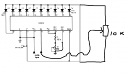
Make it look like this. You can keep the 1.2k because that prevents the total resistance going below that, even with the pot on minimum resistance.
The pot at the right should enable all the LED's to light as you turn it. When you get your meter you can then check how much voltage is needed to light them all as you turn the pot by measuring the input voltage to the chip.
The pot at the right should enable all the LED's to light as you turn it. When you get your meter you can then check how much voltage is needed to light them all as you turn the pot by measuring the input voltage to the chip.
Attachments
- Status
- Not open for further replies.
- Home
- General Interest
- Everything Else
- lm 3915 vu meter problem.