But if the supply voltage isn't high enough for the designed circuit, the drive current for the LEDs won't be high enough without adjusting resistor values.
Mike
Mike
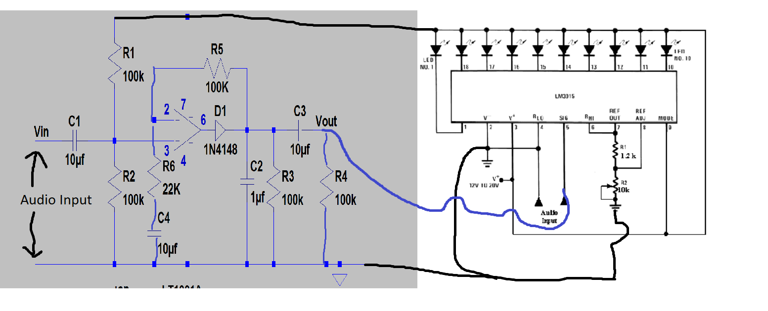
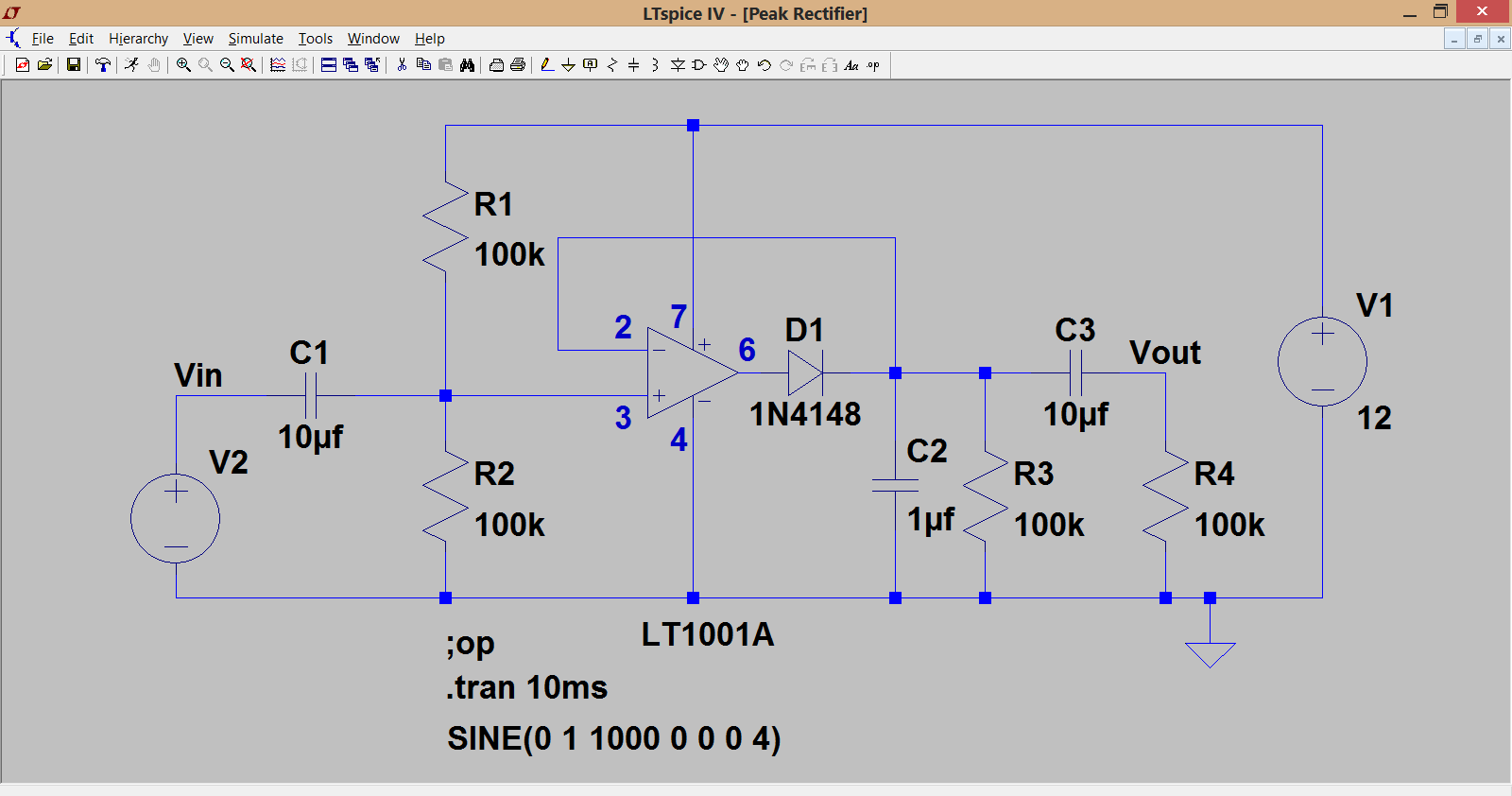
Yes, the top wire is the positive rail. That goes to pin 7 of the opamp. Pin 4 of the opamp connects to the negative rail (which is really ground or 0 volts here). Its confusing because we have the pins on the LM3915 as well which happen to be similar.
The blue triangle is a just a ground symbol that the circuit simulator needs to work with.
The blue triangle is a just a ground symbol that the circuit simulator needs to work with.
But if the supply voltage isn't high enough for the designed circuit, the drive current for the LEDs won't be high enough without adjusting resistor values.
Mike
The data sheet reads that the outputs are current limited and programmable and so supply variation shouldn't alter things so much 🙂 That's how I take it. 9volts, 12 volts, 15 volts, all are plenty high enough for this. The calculated current should be independent of supply voltage because it uses the internal bandgap reference as its starting point.
i think u didint understand my question. I mean the top wire of the opamp which is positive so i can simply connect this to my positive rail? i mean this http://d32zx1or0t1x0y.cloudfront.net/2009/06/breadboard_3_lrg.jpg
And the bottom wire of the opamp in this circuit is connected to the pin 2 and pin 7 . so can i connect to the negative rail in the photo i shown you?
and about that triangle - should i connect it with something or i just leave it alone?
And the bottom wire of the opamp in this circuit is connected to the pin 2 and pin 7 . so can i connect to the negative rail in the photo i shown you?
and about that triangle - should i connect it with something or i just leave it alone?
Yes, that is exactly what you do. Pin 7 of the opamp goes to the positive rail. The bottom wire of the opamp that goes to ground is pin 4 of the opamp. That connects to your ground rails. The triangle is just a symbol for the simulator program so ignore it.
That's it for today 🙂
That's it for today 🙂
yup thanks so much ! u helped ALOT ALOT ALOT! i wish u everything best 😀 ur such a good man.. I will try to do that opamp for now 🙂 i will post my results
Hello there again. http://i.imgur.com/McbLp8p.png are the positives of the capacitors are correct? And one more thing : there are 2 types of opamp 741 in my local shop
UA741CN DIP8 and LM741CN/NS DIP8
is there are any difference?
UA741CN DIP8 and LM741CN/NS DIP8
is there are any difference?
Yes, that's it. Remember that diagram didn't scale correctly and the vertical traces from pin 7 and pin 4 are missing. Pin 7 to supply, pin 4 to ground.
For the opamp just get the cheapest one. They are just different manufacturer codes. uA used to be Fairchild and LM National Semiconductor.
For the opamp just get the cheapest one. They are just different manufacturer codes. uA used to be Fairchild and LM National Semiconductor.
Like that 🙂
The striped end of the diode is the cathode and goes to C2 etc. I always found that very confusing when I first started out with electronics because a certain magazine (Practical Wireless) always drew diodes with a plus symbol on the cathode, which I found very confusing.
The striped end of the diode is the cathode and goes to C2 etc. I always found that very confusing when I first started out with electronics because a certain magazine (Practical Wireless) always drew diodes with a plus symbol on the cathode, which I found very confusing.
Yeah okayy thanks. Im waiting for my jumper wires right now from ebay ;/ im not sure if i should wield that on the board in case i do a mistake and everything will ****** ;/ should i do everything on same breadboard? if its enough place
Don't try soldering to a plug in breadboard, that will just ruin it. Its only a small circuit and so should all fit OK on a board like you showed in an earlier picture.
http://upload.wikimedia.org/wikipedia/commons/d/d2/Solderless_Breadboard_with_LEDs.jpg
yeah mine looks like this. it should fit
yeah mine looks like this. it should fit
Yo im waiting for my parts now and build a little 5 led vu meter. All leds seems working right but they doessnt look like they just normaly glow, they just blink really fast and i can see it is that okay or thats something wrong?http://3.bp.blogspot.com/-QzQlt4ozx...1600/Screen+Shot+2012-12-28+at+3.14.57+AM.png
used this scheme except that resistor near leds.
used this scheme except that resistor near leds.
I've never used that IC and so don't know how the circuit is supposed to behave. There doesn't appear to be any means of sampling and 'holding' the input voltage.
Hello its me again. I have build that opamp meter but i cannot see any changes. still the 5 led blinks. How can i simply test if my opamp is working ? and i quite not understand where do i connect my audio wires on that double circuit:http://www.diyaudio.com/forums/atta...21000210-lm-3915-vu-meter-problem-capture.png
nevermind. decided to build everything from zero. so first i will try building that opamp.
http://www.diyaudio.com/forums/atta...20987547-lm-3915-vu-meter-problem-circuit.png
i will go for this one because it seems easiest but i got some questions:
1.That capacitor C1 positive connects to pin 3 of the opamp and the negative goes to positive side of battery?? I dont get it becuase in both sides are those 2 circles with + and - signs which confuses me
I'd forgotten where we were up to on this 🙂
The easiest way to test any circuitry is with an oscilloscope, it really is an essential tool of the trade.
Just looking at the circuit again and you could try this. You could try making C2 larger, say 10uf and C3 quite a lot bigger to pass the 'slow moving peaks' to the LM3915.
You can do a basic test of the opamp by measuring the DC voltages. You should have around half the supply voltage on the output pin.
- Status
- Not open for further replies.
- Home
- General Interest
- Everything Else
- lm 3915 vu meter problem.