The diagram with the diode is an input for audio. The audio earth goes to ground (-ve).
Connect the Audio signal to the in(put). Connect the end of the 1K resistor to pin 5 on the LM3915.
With a bargraph setting (pin 9 to positive) this will display the signal. Speed depends on the capacitor value.
Attempt at a video (avi) of the VU meter
May be best to right click and download the avi file I think, does not work too well in Firefox with VLC for me.
@ 7mb
alan
Last edited:
ok. so instead of connecting audio straight to pin 5 i connect it to diode and resitors as shown
ok. so instead of connecting audio straight to pin 5 i connect it to diode and resitors as shown
Yes, provided the chip is correctly wired this will work off a 9v battery.
Mooly, you have the patience of a saint.
aggree. No one else survived my questions that long.. I know that i should try to do it by myself and stuff but believe me im so bad, most things i try to do by myself 99% i fail. The god didint give me enough brains and my logical thinking is also very very bad..
Everybody is special.
You have to be systematic while doing such an adventure.
And you have to check each net and complete all the connections at each point(net) without going to the other net. First check pin 1 is correct.
e.g. pin 8 connects to R1 and R2...done it then the net is connected. Pin8 issue is over.
Gajanan Phadte
in that circuit Spiny showed me. where i need diode , 2 resistors and capactior. My input is pin 5 so i dont get it.. I connect that diode to pin 5(input) and that resistor 1K ohms also gues to pin 5? do i get it right?
Yes, the audio input goes to the left side of the diode. The right (striped side) goes to pin 5 via the 1k.
http://i.imgur.com/PcWzCWS.jpg
you can see a little diode which is connected to 3 componens : resistor and capacitor whose are connected to ground and other resistor which is connected to jumper to pin 5. and other side of diode is connected to input of audio . everything seems right?
you can see a little diode which is connected to 3 componens : resistor and capacitor whose are connected to ground and other resistor which is connected to jumper to pin 5. and other side of diode is connected to input of audio . everything seems right?
You need to do the test I mentioned way back using a meter and with pot set up on the input to give a variable DC input voltage. That would let you check that all the LED's light and at what voltage.
crowdfunding...
patience is a virtue and Mooly has my vote as forum patriarch of patience
lukutis what value is the capacitor your using?
patience is a virtue and Mooly has my vote as forum patriarch of patience
lukutis what value is the capacitor your using?
in that circuit Spiny showed me. where i need diode , 2 resistors and capactior. My input is pin 5 so i dont get it.. I connect that diode to pin 5(input) and that resistor 1K ohms also gues to pin 5? do i get it right?
the Audio input goes to the diode, the resistor to Pin 5
the audio ground goes to negative
To test Connect the diode input to +ve this puts 9v on the input. All the leds should light if pin 9 is connected to positive (bar graph mode)
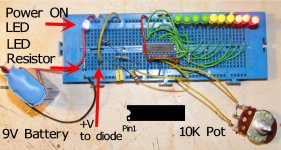
Here is the LM wired up to test.
I suggest you put a led and resistor (1k-5K resistor will do) from positive to negative as a power on indicator, this will show if the battery is connected and if it has some power in it.
Check the IC is the right way round. Pin 1 is the end with a small cut out/ dent usually semicircular. some have a dot molded by pin 1
Do connect Pin 9 to positive.
alan
Ive used a 47K to stop the blue led used blinding the camera 🙂
Attachments
Can you check the resistor from Pin7 to pin 8. it should be Brown Black Red + Gold or silver. your picture suggests Orange as the 3rd band
If its orange then its a 10K not 1K
the original Gif suggests 1.2 K thats Brown Red Red + Gold/silver
(Brown Red Orange is 12K)
the value of the resistor from the diode to negative should be around 100K , the one to pin 5 @ 1K
I can not read the values from the photo I'm afraid
Is there a wire from pin 4 to negative? there appears to be one from pin 2 to negative.
To stop confusion have Positive only at the top of the breadboard and Negative only at the bottom. Do not use the extra power rails. Put a power light from + to - to tell you the battery is connected.
Last edited:
If you connect input pin 5 to pin 3(short pin5 to pin 3 with a jumper), what happens.
Gajanan Phadte
Edit: Have you connected pin9 to pin3 for bar mode.
Gajanan Phadte
Edit: Have you connected pin9 to pin3 for bar mode.
Last edited:
Spiny
Resistor between pin 7 to pin 8 is 1k
resistor from diode to negative is 100k and other resistor from diode is 1k. capacitor im using is 1uf and capacitor positive connects diode cathode and negative to ground :/ When i connect my audio to pin 5 everything works but only 6 leds blink... when i connect to diode all the leds immiadetly turns off
- Status
- Not open for further replies.
- Home
- General Interest
- Everything Else
- lm 3915 vu meter problem.