well i can try that :d do i need any resistor to put to the circuit so my leds wont burn? and how do i connect 2 batteries? just connect another one 9V batter to ground and + rails of my breadboard?
ok you don't understand series and parallel connections....
sorry i think that you need to get more familiar with the basics of electronics which i don't have the time to teach you.
good luck in your endeavours.
sorry i think that you need to get more familiar with the basics of electronics which i don't have the time to teach you.
good luck in your endeavours.
well i can try that :d do i need any resistor to put to the circuit so my leds wont burn? and how do i connect 2 batteries? just connect another one 9V batter to ground and + rails of my breadboard?
Like this,
Connecting Batteries in Series or Parallel
the lm3915 and the others in the LM39xx familly will happly run on a 9v battery accordin to the data sheet even down to 3v.
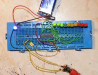
If you can manage a photo of the breadboard layout you are using maybe we can see the problem. I'll try and post one soon on a typical breadboard
alan
If you can manage a photo of the breadboard layout you are using maybe we can see the problem. I'll try and post one soon on a typical breadboard
alan
tell me if u dont understand those connections i will tell you what i connected there and stuff.
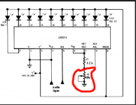
Both pin 2 and pin 4 should go to negative, it looks like only pin 2 does.
pin 9 should go to positive for a bargraph or do not connect for a dot mode.
Make sure the LED's are the right way round >Flatside of the leds to the Chip other side to positive.
A voltage on the wire to pin 5 should light the leds. You can try this by connecting another variable resistor (potentiometer) one side to positive(+) one to Negative(-) and then the middle to pin 8
this will allow you to adjust the voltage from @ 0 to @9 volts and see the leds light.
once this works we can add the few parts needed to make it work on music signals
alan
looks like the potentiometer is connected to pin 8 and if i'm looking at it right there's a loop that forms a short across the pot...
pin 9 (can't tell) appears to have no connection so it's in dot mode...
pin 9 (can't tell) appears to have no connection so it's in dot mode...
staring at this I agree I think pin8 is grounded, my first guess was pin 9 grounded.
So Disconnect the wire from pin 8 to ground
Pin8 connects to the Potentiometer
Pin 8 also goes to one end of the resistor, the other end to pin 7. I think that is done on the board.
One suggestion to the OP make all + leads red and all - leads blue this makes it easier to troubleshoot and less likely to connect the wrong way.
Try and find a cheap digital multimeter they can be had for a few euros if you look.
Last edited:
I know this probably sounds obvious (this is aimed at lukutis 🙂) but it can help to look at each pin in turn on the IC starting at pin 1 and then confirming and checking it goes exactly where it should. Go around the IC methodically and tick them off as you check each one.
Just looking at it all as a whole and you miss things.
Just looking at it all as a whole and you miss things.
i have pin 2 connected with pin 4 but only pin 2 connected to ground. Do i need to connect pin 4 with ground also? And i dont need connection from pin 8 to negative just to the middle leg of variable resistor?
well we have to assume that all your connections are good (some breadboards will give you connection problems especially if you use different diameter wires in adjacent holes)
if pin 2 and 4 are connected and 2 see's ground then 4 should be grounded (only real way to know is to verify with a multimeter set to low ohm's scale)
tying pin 8 to the pot wiper will change the sensitivity (which from what your telling us isn't sensitive enough)
if pin 2 and 4 are connected and 2 see's ground then 4 should be grounded (only real way to know is to verify with a multimeter set to low ohm's scale)
tying pin 8 to the pot wiper will change the sensitivity (which from what your telling us isn't sensitive enough)
pin8 goes to the variable resistor and the middle leg of the variable resistor goes to negative (ground) (as per the original diagram in the first post)
In this design the negative is the same as ground.
In this design the negative is the same as ground.
spiny do u mean i need to connec middle leg of variable resistor to the ground? Because my vu meter circuit does not show that 😀 Yes turk 182 ur tottaly right.. Its not sensitive enough .. and i need to make opamp but without multimeter there is no way i can check if its working or no 😱
what is your audio source?
so if you take everything off pin 8 install a jumper to ground you don't get leds further up the ladder to light up?
try hooking pin 9 to b+ (your positive supply point) and describe to me what you see?
so if you take everything off pin 8 install a jumper to ground you don't get leds further up the ladder to light up?
try hooking pin 9 to b+ (your positive supply point) and describe to me what you see?
turk? so in this case u told me u want me to disconnect the variable resistor which is connected to pin 8 ? just leave pin 8 to ground and thats it? audio source is just from the pc.
so does your meter correspond to the levels on your computer.
cause you can't meter what isn't there.
and yes pin 8 to ground.
crowd funding anyone...lukutis still needs a meter!!!
cause you can't meter what isn't there.
and yes pin 8 to ground.
crowd funding anyone...lukutis still needs a meter!!!
The original diagram shows the middle leg of the variable resistor connecting to one end of the variable and ground. The other end of the variable goes to pin 8
As turk suggests connect pin 9 to positive to make a bargraph.
the meter is quite sensitive without an opamp and will work off the output of a soundcard.
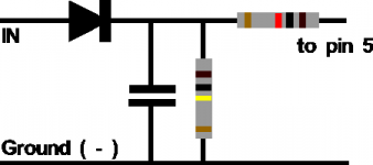
To make it work though I feel the original circuit is not much use and you need a diode, a capacitor and 2 resistors, see image attached.
This will give only positive voltage to the VU meter, the value of the capacitor will alter the decay time of the bar graph, try 0.1uf > 1 uf the larger the value the slower the meter.
As turk suggests connect pin 9 to positive to make a bargraph.
the meter is quite sensitive without an opamp and will work off the output of a soundcard.
To make it work though I feel the original circuit is not much use and you need a diode, a capacitor and 2 resistors, see image attached.
This will give only positive voltage to the VU meter, the value of the capacitor will alter the decay time of the bar graph, try 0.1uf > 1 uf the larger the value the slower the meter.
Attachments
The original diagram shows the middle leg of the variable resistor connecting to one end of the variable and ground. The other end of the variable goes to pin 8
Yes i have them connected like u said. Where does this diode connects? i didint quite understand those IN and OUT
Yes i have them connected like u said. Where does this diode connects? i didint quite understand those IN and OUT
- Status
- Not open for further replies.
- Home
- General Interest
- Everything Else
- lm 3915 vu meter problem.