Is there an schematic anywhere for the LJM-Audio L20.5 Amplifier?
Can you provide any asc files?
Can you provide any asc files?
Sorry: second try
Hello
This is my LJM-Audio L20.5 Amplifier.
I let pictures speak first.
https://www.diyaudio.com/forums/att...aar/835638d1587311061-ljm-audio-l20-5-amp-jpg
https://www.diyaudio.com/forums/att...87311061-ljm-audio-l20-5-amp-innenansicht-jpg
https://www.diyaudio.com/forums/attachments/vendor-s-bazaar/835640d1587311061-ljm-audio-4-ohm-jpg
https://www.diyaudio.com/forums/attachments/vendor-s-bazaar/835641d1587311061-ljm-audio-8-ohm-jpg
https://www.diyaudio.com/forums/att...r/835642d1587311061-ljm-audio-vg-m2-l20-5-jpg
@LJM Congratulations, with this Amplifier board you didn't promise too much
This is by far the best Amplifier I've ever built.
Thank you very much for that
Michael


Looks good. I’m a novice so.....
1) May I have the link for the SMPS?
2) Is there a THD vs noise chart?
3) How about SINAD?
Looks good. I’m a novice so.....
1) May I have the link for the SMPS?
2) Is there a THD vs noise chart?
3) How about SINAD?
4) Is there speaker protection circuit?
Last edited:
Hello,
🙄 I can answer questions 1 + 4
600W SMPS
600W DC +/-58V Amplifier Switching Power Supply Board Dual-voltage Amp PSU | eBay
Greetings
Michael
🙄 I can answer questions 1 + 4
600W SMPS
600W DC +/-58V Amplifier Switching Power Supply Board Dual-voltage Amp PSU | eBay
Greetings
Michael
Hello,
🙄 I can answer questions 1 + 4
600W SMPS
600W DC +/-58V Amplifier Switching Power Supply Board Dual-voltage Amp PSU | eBay
Greetings
Michael
Any link to the casing? I have not found those perforated metal base online also.
Can the power supply be split to supply both I wonder if I don't driver 4 ohm load.
Seems to be the Disspante Case from modushop.bizAny link to the casing? I have not found those perforated metal base online also.
One power supply should be enough on 8 Ohm, since you have only the half output power.Can the power supply be split to supply both I wonder if I don't driver 4 ohm load.
Maybe by reducing the static current, as noted by LJM?
See LJM comment on that here: [wiki=http://www.diyaudio.com/forums/solid-state/199093-l20-amp-njw0302g-post3841646.html]%[/wiki]
Must copy + paste that link
Hello,
I have a problem:
I bought 2 L20SE bass amplifiers on Aliexpress. Bass Gun L20 SE A1943 C5200 200W 8R Mono Assembled AMP Amplifier Finished Board|Amplifier| - AliExpress
I have now put them into use.
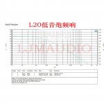
However, they are not bass amplifiers.
The frequency response is straight up to 20 kHz.
I have asked the seller for an electronic diagram of the bass amplifier, but I have not received an answer.
Does anyone have a diagram or know where I can find it?
Thank!
I have a problem:
I bought 2 L20SE bass amplifiers on Aliexpress. Bass Gun L20 SE A1943 C5200 200W 8R Mono Assembled AMP Amplifier Finished Board|Amplifier| - AliExpress
I have now put them into use.
However, they are not bass amplifiers.
The frequency response is straight up to 20 kHz.
I have asked the seller for an electronic diagram of the bass amplifier, but I have not received an answer.
Does anyone have a diagram or know where I can find it?
Thank!
There's no problem with that... Main purpose of a bass amp is the ability to amplify the lowest tones in music. Most of those amps are capable of frequencies over 20K. Limiting bandwidth if required is done before the powerstage.The frequency response is straight up to 20 kHz.
Thank!
Hello,
I have a problem:
I bought 2 L20SE bass amplifiers on Aliexpress. Bass Gun L20 SE A1943 C5200 200W 8R Mono Assembled AMP Amplifier Finished Board|Amplifier| - AliExpress
I have now put them into use.
However, they are not bass amplifiers.
The frequency response is straight up to 20 kHz.
I have asked the seller for an electronic diagram of the bass amplifier, but I have not received an answer.
Does anyone have a diagram or know where I can find it?
Thank!
You can upload your photos. I can have a look.
Because of the l20se and l20se subwoofer versions. The appearance is the same.
I don't know if the purchasing agent is wrong. However, it can be easily modified to a bass version.
what is the gain of the board? the supplier said that 32 times (30dB) and i noticed a 330 ohm and 10kohm Ri and Rf so Ri/Rf=32, i think he is correct.. but i wonder which resistor or resistor are responsible for gain adjusment? can you show them for me on the pcb with their values so i want to increase the gain
33000/1000+1=34 GAIN.
If you don't know. You can take a picture and I'll tell you.
Because there are two versions of L7.
I'm not sure which version you are.
33000/1000+1=34 GAIN.
If you don't know. You can take a picture and I'll tell you.
Because there are two versions of L7.
I'm not sure which version you are.
Maybe you are talking about the L20 instead of L7?
Anyway I purchased recently a new L7 pair and the boards are slightly different than the older ones.
I have found some differences between the regular L20SE and the bass version:
C1 from 330p to 2.2uF and R15 from 330 ohm to 150 ohm.
I think that is all.
Am I right ljm_ljm?
C1 from 330p to 2.2uF and R15 from 330 ohm to 150 ohm.
I think that is all.
Am I right ljm_ljm?
Hello there!
Does anyone knows sound differences between LJM L12-2 and L20SE? I got two L12-2 and this is really clean with a lot of details. I've heard that L20SE is more pleasant to listen to. Is this correct?
Thanks
Does anyone knows sound differences between LJM L12-2 and L20SE? I got two L12-2 and this is really clean with a lot of details. I've heard that L20SE is more pleasant to listen to. Is this correct?
Thanks
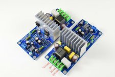
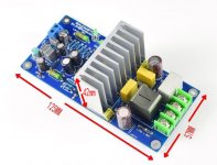
The latest version of the photo.
Because I found that the OSCON capacitor is in a relatively hot position. It may be damaged after working for a long time.
And it can't be seen from the outside.
So in some places. I replaced the electrolytic capacitor with a higher voltage. 50V-63V。
They are used for filtering capacitors. More capacity. Higher withstand voltage. So performance doesn't degrade. It will be improved.
The input signal capacitor has a very low working temperature. So the OSCON capacitor is still used.
PCB adopts two layers.
Attachments
Hello there!
Does anyone knows sound differences between LJM L12-2 and L20SE? I got two L12-2 and this is really clean with a lot of details. I've heard that L20SE is more pleasant to listen to. Is this correct?
Thanks
You can consider using l20.5
L20.5 is an upgrade of l12-2.
You can consider using l20.5
L20.5 is an upgrade of l12-2.
Do you have a website with build instructions/suggested implementations for any of your products?
Is this the most direct way to purchase?
?????-ljm ?????????-???
Which is your favourite amp you sell? 🙂
Does it have AUX voltages?Hello,
🙄 I can answer questions 1 + 4
600W SMPS
600W DC +/-58V Amplifier Switching Power Supply Board Dual-voltage Amp PSU | eBay
Greetings
Michael
- Home
- Vendor's Bazaar
- LJM Audio