My mx50x2 is powered with +/-45VDc with no problems, my step father's one is +/-47.5VDc (Marantz pm-45 psu) and is also fine.
Pay attention to Ncc5551 pinout...
If you do not already got 2sc5200 you also can try Mjl21194 if you have to buy them, slowest (so less prone to oscillations) but pretty cheap and robust, good performers.
Pay attention to Ncc5551 pinout...
If you do not already got 2sc5200 you also can try Mjl21194 if you have to buy them, slowest (so less prone to oscillations) but pretty cheap and robust, good performers.
@Kozard
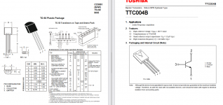
Be careful, NC5551 have different pinout arrangement than the 5551 available on western market.
Maybe you would like to check each one's datasheet.
Keeping under +-40VDC is a safety measure that gives peace of mind, good sound and stay away of troubles. The output power is still enough to drive any modern loudspeaker near 90 dB/1W/ 1m.
Needing more power, better watching at other projects or use bi-amplification IMHO.
While the pin numbering is reversed (1-2-3 left to right vs right to left) I think the actual pinout is the same for TTC004 and NC5551 (see attached).
I don't need more power, so I can use lower voltage.
However I would like to know (for 8 Ohms) the relationship between supply voltage and output peak power for the MX50x2 and L7.
The bigger issue for me is that I have defunct receivers with high quality power transformers that are suited for +/- 50V not +/- 40V.
Attachments
My mx50x2 is powered with +/-45VDc with no problems, my step father's one is +/-47.5VDc (Marantz pm-45 psu) and is also fine.
The odd thing is that one of the two boards burned up at +/- 50V and the second did not. Same power supply and same heat sink and the heat sink was cold. Burned up in the first few seconds of power up.
So I think it might be something specific to this sample or batch. Hence my interest in replacing the drivers and output transistors with known sources (authorized distributors) and ones that I have matched in my transistor tester.
If you do not already got 2sc5200 you also can try Mjl21194 if you have to buy them, slowest (so less prone to oscillations) but pretty cheap and robust, good performers.
I do have the real Toshiba 2SC5200 already but they were for another project. I really did not want to use up four (or eight if I do both boards) for this leaving four (or eight) 2SA1943 without pairs.
Either way I will need to place another order with Mouser or Digikey. I could consider MJL21194. So far I have bought real 2SC6145 (pairs) and 2SC5200 (pairs). I also bought (for an unrelated JLH project) TIP35/36 for slow rugged devices.
I don't think I am dealing with oscillations but these boards don't have the output Zobel network. Perhaps I should add them on the output protection relay board.
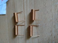
On the musical fidelity x-a50 (mx50x2 is a clone) there is a 6mm inner diameter 24 turns swg22 inductor parallel with 3r3 1w resistor (inside the inductor).
Mine are stable without but I'll ad it as soon as I receive some resistors.
EDIT // I hope we get a reply from ljm_ljm on biasing current for mx50x2...
You can check for MJW21196G, they are pretty cheap at mouser
Mine are stable without but I'll ad it as soon as I receive some resistors.
EDIT // I hope we get a reply from ljm_ljm on biasing current for mx50x2...
You can check for MJW21196G, they are pretty cheap at mouser
Attachments
Last edited:
Zoblel network is present on mx50x2 10R + yellow film 100nf cap on your pictures.
I don't know it installed on l7.
I don't know it installed on l7.
True, I was wondering if the series inductor (paralleled with a resistor) was needed too.Zoblel network is present on mx50x2 10R + yellow film 100nf cap on your pictures.
I don't know it installed on l7.
Yes.Additional security is never a bad thing.
Your speakers could say thanks some days
I was wondering for safety sake if I should just wire a series inductor (with parallel resistor) in the leads for my test speakers. Maybe with the shunt RC too. My test speakers are pretty nice and with all of the switching and testing of new boards (with limited or no protection built into the boards as they arrive) maybe it would be wise.
I don't think the length of speaker wire between the amplifier and before the inductor (and parallel resistor) would be a problem. Right?
I might even wire a fuse into my "test speaker cables" that I use with my test speakers. I guess I am a little worried after the MX50x2 some how managed to incinerate four 12A D1047 output devices.
Last edited:
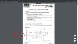
I use cheap Chinese upc1237 speaker protection boards supplied by a 12vac transformer in all my amplifier except for class d.
Each time I check it with an aa battery
Maybe you can add it to your test setup, it will protect yous speakers from dc and power on/off thump but not for oscillations problem, you can use R/L network at protection output too.
Be careful oscillations can easily fry your tweeters...
Each time I check it with an aa battery
Maybe you can add it to your test setup, it will protect yous speakers from dc and power on/off thump but not for oscillations problem, you can use R/L network at protection output too.
Be careful oscillations can easily fry your tweeters...
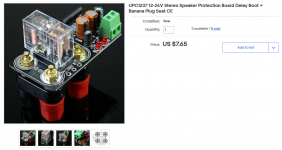
I bought one too (black) but I found that it protects for only positive offsets and not negative. I traced the schematic and found that pins one and two were mixed up in the layout of the board. The seller was no help and continues to sell the board.I use cheap Chinese upc1237 speaker protection boards supplied by a 12vac transformer in all my amplifier except for class d.
Each time I check it with an aa battery
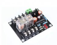
I later bought yellow ones which are pretty much identical but the pins are not mixed up. I have enclosed a picture of the yellow one that I use now. It fits the cut outs at the back of the used/defunct receiver chassis that I am using for the chassis/heat sink (and power supply when the kit can handle the voltage...)
The black one that does not work looks almost identical except the PCB is black. You would never know it does not work properly unless you tested it... ...or your speakers burned up.
Attachments

I have enclosed a picture of the black one that I bought that does not work. I found that this black PCB version protects for only positive offsets and not negative. I traced the schematic and found that pins one and two are mixed up in the layout of the board. The seller was no help and continues to sell the board.
Due to the black solder mask it is a bit hard to see but what you can do is use a volt meter to see if your uPC1237 pin 2 is shorted to ground or not. The ones with the error have pin 2 shorted to ground in the layout and the offset detection network/input is connected to pin 1 instead. (Which is a mistake and will only trigger on positive offsets.)
It looks like lots of people have bought this from lots of different named seller accounts. I would suggest that owners of black PCB versions like this should test the negative offset (not just positive) to see if their PCB has the error or not.
Attachments
There is the one I use, nothing wrong but I'll chack again...
That is a different black board, not the one I bought. I just posted a picture of the one with the problem.

Just finished this for a friend. Work perfect from start. Transformer 2 x33 vac. 2 x47 vdc. It's only for midrange and treble.
From what I can tell in the photo all standard caps & resistors that came with the kit? Same with the transistors?Just finished this for a friend. Work perfect from start. Transformer 2 x33 vac. 2 x47 vdc. It's only for midrange and treble.
You are right about that. I am a bit concerned it will sound to bright. But it had to be cheap. He is about 80 so maybe he don't hear the magnetic metalfilm resistors. I have some other modules with Takman Carbon resistors. But I need more components for them.
Well if +/-47V is safe maybe I either pull the transformers and buy 32 VAC transformers or perhaps try a CRC followed by TIP35 & TIP36 series regulators with the R chosen to minimize dissipation in the series regulator pass devices at maximum current. I hate to go with such complication but I can not explain the MX50x2 burning up.
The MA9S2 has no problems with the higher voltages and the same heatsink even though it is a hotter amplifier. (And most likely is using fake 2SC5200 and 2SA1943 devices. At least they don't look like what Mouser shipped me...)
Either that or I rebuild the MX50x2 with known good/genuine devices and then take my changes with the higher voltages a second time with both the MX50x2 and the L7.
Very nice sounding this morning in Copenhagen. Trying on very cheap Dali speakers for security sake.
On the musical fidelity x-a50 (mx50x2 is a clone) there is a 6mm inner diameter 24 turns swg22 inductor parallel with 3r3 1w resistor (inside the inductor).
Mine are stable without but I'll ad it as soon as I receive some resistors.
EDIT // I hope we get a reply from ljm_ljm on biasing current for mx50x2...
You can check for MJW21196G, they are pretty cheap at mouser
Mx50x2 bias voltage.
It can be measured. Voltage between d1047 B E.
Generally 530mv. We don't need to adjust it.
Well if +/-47V is safe maybe I either pull the transformers and buy 32 VAC transformers or perhaps try a CRC followed by TIP35 & TIP36 series regulators with the R chosen to minimize dissipation in the series regulator pass devices at maximum current. I hate to go with such complication but I can not explain the MX50x2 burning up.
The MA9S2 has no problems with the higher voltages and the same heatsink even though it is a hotter amplifier. (And most likely is using fake 2SC5200 and 2SA1943 devices. At least they don't look like what Mouser shipped me...)
Either that or I rebuild the MX50x2 with known good/genuine devices and then take my changes with the higher voltages a second time with both the MX50x2 and the L7.
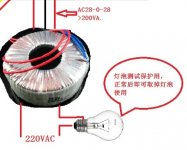
You can connect a light bulb in series with 220 v.
It's easy.
As long as the light bulb is not very bright. The DC voltage of out GND is less than 50mV DC.
Listen to the sound again.
no problem. Remove the bulb.
If there's a problem, the bulb stays on. And it can avoid damaging transistors.
Attachments
- Home
- Vendor's Bazaar
- LJM Audio