Not aware of anyone trying to elucidate a theory of film cap sound quality vs that of electrolytics. Don't know why electrolytics sound the way they do (grainy), except I think the ESL and ESR level of modeling we use to describe caps may not be quite low level enough to explain a theory of why film caps sound so different. Could have to do with the ladder network model of electrolytics, but even then not so sure that explains it all. Bottom line, my experience on the above is purely empirical. Film caps usually seem to help sound quality when low ESR or standard electrolytics are used. Even for some power supplies reputed not to need film caps, they may help sound quality anyway. That may not always be the case in the future of course. And, it is always possible that a fast regulator not designed to work with a lot of film caps at the output could go unstable. That is why I always attach test film caps at the load and not at the power supply. They help the load more than way and probably bother the regulator less (if it is bothered at all).
Regarding the impedance of film caps, I use around 100uf of them on each of the +-15v analog rails. That is almost getting up close to sometimes used electrolytic values of capacitance.
Regarding the impedance of film caps, I use around 100uf of them on each of the +-15v analog rails. That is almost getting up close to sometimes used electrolytic values of capacitance.
Last edited:
I've not experienced 'graininess' of electrolytics myself, when the sound is 'grainy' it has been because I've not used enough electrolytics to achieve a low enough impedance. This only happens with opamps where they generate their own supply noise by virtue of running classAB. Powering discrete circuits running classA I've not experienced any 'graininess' from electrolytics.
So it seems we have no leads (in terms of theories) to understand better why film caps on the power supplies make for a better sound when standard circuit theory says they only make a difference to the supply impedance in a relatively narrow band of frequencies which are generally ultrasonic. However if the electrolytic on the supply is of the order of 100uF then sure, adding film caps will lower the impedance within the audio band as 'lytics in that range of values will have relatively high ESRs (of the order of low hundreds of milliohms).
So it seems we have no leads (in terms of theories) to understand better why film caps on the power supplies make for a better sound when standard circuit theory says they only make a difference to the supply impedance in a relatively narrow band of frequencies which are generally ultrasonic. However if the electrolytic on the supply is of the order of 100uF then sure, adding film caps will lower the impedance within the audio band as 'lytics in that range of values will have relatively high ESRs (of the order of low hundreds of milliohms).
Don't know if the graininess comes from crossover distortion or not. Allo Katana dac supposedly uses Sparkos class-A output opamps. They sounded grainy running from an external linear PS until I added film caps to the +-15v rails. Definite step up in sound quality, as others have confirmed.
When the output stage is a push-pull one (as I presume the Sparkos opamp is), running classA doesn't guarantee no modulation of the rails. To get zero load-induced noise a push-pull stage has to run bridged i.e. two are needed in anti-phase and the load current runs between them.
No, crossover distortion isn't the issue as far as I can determine - load current induced modulation of the rails is.
No, crossover distortion isn't the issue as far as I can determine - load current induced modulation of the rails is.
With the TDA1387 in balanced config and a passive output stage I found there was still some audible benefit to the larger PP caps(40uf+12uf+2.8uf), more so than having them on my HPA supply.
They also worked well in a 9038 DAC op amp supply but the op amps were dealing balanced signals aswell, additionally the opa1612 were apparently running in Class A from DAC offset.
They also worked well in a 9038 DAC op amp supply but the op amps were dealing balanced signals aswell, additionally the opa1612 were apparently running in Class A from DAC offset.
That was putting the film caps on the TDA1387 supply rail? Any other caps on there before adding those PPs?
yes, after the reg there was 220uf electrolytic plus some <0.1uf PP caps, at each DAC chip (of 12) there is a 10uf oscon, and also some tantalums on LT3045 board.
Ah, so nothing very low ESR on the rails prior to the PPs. And running passive I/V its very sensitive to supply noise.
Do you mean that without measurements its not safe to say the circuit is not reacting in some other way to the low ESR caps?
No, that's not my meaning. I mean to say its no big surprise that the film caps had a positive effect when they're going to be the dominant factor in the supply impedance across the top of the band. Mind you, 12 10uF OSCONs ought to have a paralleled ESR pretty low. Got a picture of the layout?
ok, so its possible with a large amount of small paralleled electrolytics you could achieve something similar, thats something to explore.
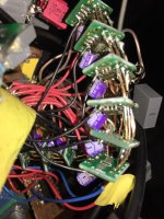
I cant take a pic right now but will soon, its a bit of a mess with everything wired point to point.
I cant take a pic right now but will soon, its a bit of a mess with everything wired point to point.
The chips are on DIP8 adapters, and oscon soldered directly to pins/pad, its satisfying that this kind of rough circuit building can allow even closer decoupling with the oscon than what possible on a PCB.
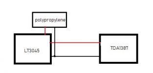
From the LT3045 board output there is a twisted pair to the huge film caps, the chips have individual wires also directly to the LT3045 output, instead of the legs of the film caps as the chip power wires are shorter this way with the big film caps out of the way, if that makes sense.
From the LT3045 board output there is a twisted pair to the huge film caps, the chips have individual wires also directly to the LT3045 output, instead of the legs of the film caps as the chip power wires are shorter this way with the big film caps out of the way, if that makes sense.
Attachments
Does your new transformer's primary have a connection to ground? if not then you must have encountered the same right channel noise issue I mentioned earlier, with either headphones or a transformer floating between the balanced TDA1387s outputs, but not with typical i/V resistors to ground or active I/V.
High impedance headphones driven directly by the DAC output in this way sounded great, but for normal use was kind of ruined by low level noise.
High impedance headphones driven directly by the DAC output in this way sounded great, but for normal use was kind of ruined by low level noise.
Thanks for sharing the pic @laserscrape - until now I thought my DAC creations were excessively 3D but yours knocks mine into a cocked hat. I shall have to raise my game 😀
In respect of the trafo - the primary is a centre-tapped one designed for being driven differentially. Its intentionally like this so it can handle the DAC's (DC) bias current without running into saturation (its a low saturation flux, high permeability core). The centre tap goes to ground yes. I can see why you'd get noise problems if you 'float' a load between two outputs - there's no way to keep the common-mode voltage under control. When I disconnect the ground on my trafo I do get noise yeah but I think its on both channels.
In respect of the trafo - the primary is a centre-tapped one designed for being driven differentially. Its intentionally like this so it can handle the DAC's (DC) bias current without running into saturation (its a low saturation flux, high permeability core). The centre tap goes to ground yes. I can see why you'd get noise problems if you 'float' a load between two outputs - there's no way to keep the common-mode voltage under control. When I disconnect the ground on my trafo I do get noise yeah but I think its on both channels.
Abraxalito, did you ever post the BOM for PhiDAC? If not, can you? I am parting out the 10x kit you sent me into lots for further distribution. I'd like to have something to use to check my work.
To those who PM'ed me about kits: apologies, this is taking much longer than I expected (plus had some personal stuff come up further reducing my time). I'm hoping to be done with the first batch this weekend (I know I said that before, hope is the operative word). I haven't even started the second batch yet, so more patience please.
These two batches consume nine of the 10 kits Braxy sent me, and I'm keeping one for myself.
Thank you Abraxalito for your work, and thank you everyone else for waiting on me to part out these kits!
Thank you very much Matt for your patient work in spreading your kits around, that's the spirit of PhiDAC. Its surprising how time-consuming dealing with kits is.
The BOM is attached to this post : lingDAC - cost effective RBCD multibit DAC design
The BOM is attached to this post : lingDAC - cost effective RBCD multibit DAC design
Thank you very much Matt for your patient work in spreading your kits around, that's the spirit of PhiDAC. Its surprising how time-consuming dealing with kits is.
I have a newfound respect for all the folks who have ever assembled kits for group buys! But this community has given me so much, it's the least I can do to give back a little bit.
The BOM is attached to this post : lingDAC - cost effective RBCD multibit DAC design
A couple questions:
- ID=29, "NF", C14,C26 - these were missing from the kit, are they still needed? If so, what value should they be?
- ID=38, 1800u, C10, C11, C21, C22 - C10 and C11 came as 1800u, but C21/22 are 1000u, is that OK?
Thanks again!
The 'NF' (no fit) capacitors are there because some people may want a different frequency response for the filter, particularly if they don't run NOS. The stock filter gives an HF boost which undoes the 'NOS droop' but if you run 2X or 4X OS you'll want less boost.
As for the caps I found the 1000uF Panasonics to sound best as output coupling caps (C21,C22). Hence I changed to those from 1800uF (which are Sanyo copies I believe).
As for the caps I found the 1000uF Panasonics to sound best as output coupling caps (C21,C22). Hence I changed to those from 1800uF (which are Sanyo copies I believe).
@laserscrape - I've recently run into some noise issues with my paralleled DACs when feeding a transformer. I don't know if the issue is the same one you've had but it didn't only affect one channel, it was both. It took me quite some time probing around to find out that somehow the DAC chips got damaged. An easily identifiable symptom of the damage is that the pin7 voltage is way higher than it should be (1/6th of VDD). I ended up binning a fair number of chips but the noise issue seems strongly correlated with this excessive pin7 voltage. I wonder if its possible to damage chips by inductive 'kick' from the transformer so I've added RC snubbers across the primary windings. I've not had any failures subsequently but if I do, I'll be sure to post here.
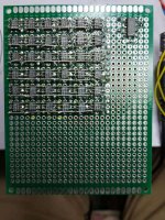
Here's a prototype coming together of a 6*6 'matrix' of DAC chips, running 2 * 18 in parallel, designed to feed a CT transformer (EP17). As I've mentioned already, SQ with this relatively simple I/V circuit is very promising, somehow there's more emotional connection to the music and bass seems more powerful. I'm continuing experiments with different ways to parallel chips.
Here's a prototype coming together of a 6*6 'matrix' of DAC chips, running 2 * 18 in parallel, designed to feed a CT transformer (EP17). As I've mentioned already, SQ with this relatively simple I/V circuit is very promising, somehow there's more emotional connection to the music and bass seems more powerful. I'm continuing experiments with different ways to parallel chips.
Attachments
- Home
- Source & Line
- Digital Line Level
- lingDAC - cost effective RBCD multibit DAC design