Son of PhiDAC - PhiDAC SE
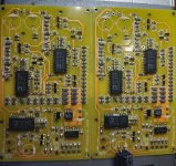
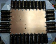
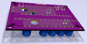
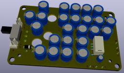
Here's a couple of pics of the next-generation design coming along.
The weakness of PhiDAC subjectively (to my ears) is evident with choral material in that massed voices tend to become rather hazy or blurred. The experiments I did earlier with the 'towers' of caps fixed that on PhiDAC but the build method was completely impractical for anyone other than a die-hard DIYer.
So PhiDAC SE has been developed to provide a slightly more practical way to get that cleanliness on choral works which the original PhiDAC lacks. The rail impedance is lowered by using more caps but the caps aren't fitted to the main board - doing that doesn't look like a particularly cost-effective route. For one it takes the board size well above the 10*10cm lowest cost board ceiling. So I'm playing with ways to add caps without adding significant cost-up.
The pics show a couple of PhiDAC SEs under construction and a prototype attempt at a 'powerbase' using bare double-sided PCB. Its split into half, left and right channels have their own array of caps - in this case 16X Nichicon HZs. 1mm diameter solid copper wires link the two PCBs, adjacent to the power pins of the AD815.
Attachments
Last edited:
Yes...
Thank you, kind sir!
...we're certain of that.I've not done a side-by-side comparison with a WM8740 but I've modded one or two based on that chip and found, even after modding they couldn't compete with earlier incarnations of my TDA1387 designs.
Thank you, kind sir!
The negative effects on SQ of TDA1387's unfiltered NOS signal, at least with my particular HPA, are very mild but I could imagine how a proper reconstruction might help (and hurt).
The issue with NOS is largely with the active components, so stacking enough chips until there is enough current to drive HPs well enough directly seem like the most logical thing to try.
The idea of creating differential output with inverted data would suit this too, as creating identical reconstruction filters for the differential signals seems like it would be very difficult.
Have you mentioned what your HPA is? I had a quick scan back but didn't notice any names. I've tried removing the filter in PhiDAC variants and the subjective effects vary between opamps (AD811 being amongst the best sounding without) but in no instance did I perceive an improvement from removing it.
I started off building a multiple paralleled DAC for direct current driving of headphones (my 600 ohm DT880s, needing the lowest current) but so far haven't figured out an elegant way to keep the DC offset under control so that project is sitting on the shelf somewhere with the 30-odd DACs soldered in but no output stage as yet.
I started off building a multiple paralleled DAC for direct current driving of headphones (my 600 ohm DT880s, needing the lowest current) but so far haven't figured out an elegant way to keep the DC offset under control so that project is sitting on the shelf somewhere with the 30-odd DACs soldered in but no output stage as yet.
it was XRK971's DCA, a simple class a amp, that was used for listening so far.
I was thinking if the DACs were configured for differential output the DC would cancel, though I assume you thought of that. But for single ended, a cap isnt the simple solution?
I was thinking if the DACs were configured for differential output the DC would cancel, though I assume you thought of that. But for single ended, a cap isnt the simple solution?
I tested with 4 stacked chip driving 300ohm HP directly with a cap, it worked and actually sounded decent, but there was still the I/V resistor in place before the 2200uf cap which I think was the key.
Removing I/V caused some weird issues.
Removing I/V caused some weird issues.
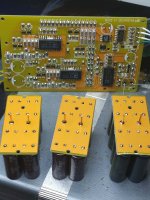
PhiDAC SE rev1
Revised boards arrived a couple of days ago for PhiDAC SE and the first one I built worked first time - at least it played music, I've not checked the flatness of the filter yet.
The extra caps on this design are fitted underneath the board via 1mm bare copper wires. The DAC still works without the off-board caps though as it has a few ceramics doing the local decoupling.
PhiDAC SE is very much at home driving headphones directly, even down to 30ohm impedance due to the far better dissipation capability of AD815s compared to AD8017s. Plus the advantage of additional caps (up to 26,000uF per channel) to provide greater output current without significant 'sag' on the rails.
Attachments
Glad to see you still working and improving the Phi DAC, abraxalito . I'm still busy (two toddlers 😛) and when I'm free again, I hope to get the PCB from you and build it to compare with the WM8740 DAC I have.
What caps are you planning to use on your PCB @obscurus?
I originally thought to attach caps on a board above the opamps on PhiDAC SE, in a similar manner to the mods I did on original PhiDAC. The cap PCBs then become 'hats' in the manner of RPi add-on boards. But when the PCBs came back I realized that the wires between them are shorter when caps are added underneath opamps rather than on top. So now I call the cap boards 'pants' 🙂 The cap board with caps at the side is a 'skirt'.
I originally thought to attach caps on a board above the opamps on PhiDAC SE, in a similar manner to the mods I did on original PhiDAC. The cap PCBs then become 'hats' in the manner of RPi add-on boards. But when the PCBs came back I realized that the wires between them are shorter when caps are added underneath opamps rather than on top. So now I call the cap boards 'pants' 🙂 The cap board with caps at the side is a 'skirt'.
What caps are you planning to use on your PCB @obscurus?
I originally thought to attach caps on a board above the opamps on PhiDAC SE, in a similar manner to the mods I did on original PhiDAC. The cap PCBs then become 'hats' in the manner of RPi add-on boards. But when the PCBs came back I realized that the wires between them are shorter when caps are added underneath opamps rather than on top. So now I call the cap boards 'pants' 🙂 The cap board with caps at the side is a 'skirt'.
I have some NCC KZH 1800uf 16V = D10mm x H25mm to use on the board.
I have some what the same setup for the board. The cap will be upside down. The exists cap will be solder backward and there will be holes for them.
Attachments
I just received several kits that Abraxalito sent me. I only plan to build one (maybe two?), so the others are available to good homes. PM me if interested, I just need you to cover shipping.
PMed !I just received several kits that Abraxalito sent me. I only plan to build one (maybe two?), so the others are available to good homes. PM me if interested, I just need you to cover shipping.
Last edited:
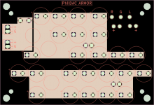
PhiDAC SE schematic
Here's the schematic of PhiDAC SE - its broadly the same design as PhiDAC but with AD8017s replaced with AD815s. The AD815 can take a higher supply (AD8017 tops out at 12V) so the supply input voltage is a bit more flexible (12-15V). Additional 'pants' capacitors aren't shown on this schematic.
The additional thermal capability of AD815 means this DAC can comfortably drive headphones directly (down to 30ohm). The output circuitry has been amended accordingly - gone is the output resistor and I'm using a couple of ferrite beads in its place, with a zobel to help with stability.
@obscurus has one of the earliest builds, I'm hoping he'll chip in with a report once he's lived with it for a while 🙂
I'm not planning any further revisions of PhiDAC - the projects I'm working on next are derivatives of lingDAC using discrete transistors rather than opamps. One DIYer messaged me about PhiDAC SE vs lingDAC and asked me to listen to them side by side to decide which was superior. The result wasn't a clear win for either one - PhiDAC SE (with its cap banks) turned out to have better LF but lingDAC won on its HF. So this led me to experiment with improvements to lingDAC's PSU....
Attachments
Last edited:
There seems to be an issue with stacking chips, I notice your DACs do not parallel any chips but other earlier ideas/designs for the TDA1387 used or at least suggested stacking.
Possibly there is some other requirement to stacking them that I am missing.
Anyway I noticed the issue of noise/distortion with TDA1387 when using single ended stacked chips, I was not sure what the cause and assumed it due to bare bones application of the chips at the time, not stacking.
After adding the XOR gate for a differential output, I attempted to root out noise/distortion issue. strangely with differential output the n/d was now consolidated to the right channel.
Because of this I was sure the it could be solved somehow, but after days of exhaustive testing (power supply, I2S, wiring, output stages, different configurations of ref pin) the only conclusion is that its the chips themselves causing this. I even tried different stacks of chips, including NXP marked types and Philips types, as always the n/d present in right channel only... very odd.
Matt_garmans design should also exhibit this issue and I noticed he vaguely mentioned a noise issue when discussing I/V stages.
I've not run across this issue in the past and I've done quite a few DACs where I've stacked TDA1387s - up to 8 high. My current design (a next generation lingDAC I suppose) is going to use a LOT of chips. Current estimate is 64 so there's a very high chance I'll be stacking chips again very soon 😀
Actually I think I am overlooking something, and that the issue with the differential outputs is seperate to single ended, will have to see....
Looking forward to seeing what you have in store with the new design, 64! I wonder how long we have till the TDA1387 supplies start drying up.
Looking forward to seeing what you have in store with the new design, 64! I wonder how long we have till the TDA1387 supplies start drying up.
I've been searching around for an engineering reason to use multiple chips and it was only after I decided I want also to use a transformer after the DACs that I came up with a justification for it 😀 With multiple paralleled chips we need a very low impedance on the output and that's what the step-up transformer is designed to give. At the same time it presents a much higher impedance to the I/V stage which distorts less as a result.
The chips themselves are so cheap here that even calling up 64 only impacts the BOM to the tune of less than $2. So it makes sense to do my best to get them all used up. The success of this design can in future be measured by the impact on spot prices of TDA1387s 😀
The chips themselves are so cheap here that even calling up 64 only impacts the BOM to the tune of less than $2. So it makes sense to do my best to get them all used up. The success of this design can in future be measured by the impact on spot prices of TDA1387s 😀
If you plot, over time, the number of tda1387 chips used in Abraxalito's designs, I think you'd have a nice sinusoidal graph. 😉
At any rate: this weekend, I intend to sort out the PhiDAC kits Abraxalito sent me, and ship them out to people who are interested. Please PM me if you're interested in receiving a kit (if you haven't already).
At any rate: this weekend, I intend to sort out the PhiDAC kits Abraxalito sent me, and ship them out to people who are interested. Please PM me if you're interested in receiving a kit (if you haven't already).
- Home
- Source & Line
- Digital Line Level
- lingDAC - cost effective RBCD multibit DAC design