
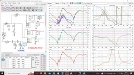
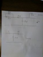
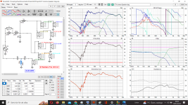
Here is how it looks with that xover, twe out and in phase.Check this out. I drew the schematic in an awkward way, but it is essentially correct, I think. Only 10 parts in the x-over.
Attachments
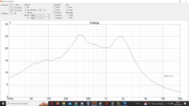
Ouch! 😱 Post #82 looks like a mountain range.
It's cool that you have truly made this your own x-over, should you decide to assemble it!
(In fairness, the 5mH in my sim was supposed to be .5mH)
But this is even better, as I didn't actually tell you how to do it. You can claim it as all yours, if that kind of thing appeals to you.
Extra parts is not a bad thing, if they offer an advantage. It sure is easier to assemble 5 than 16 though!
Last edited:
hahaha, yes a nice mountain profile!Ouch! 😱 Post #82 looks like a mountain range.
It's cool that you have truly made this your own x-over, should you decide to assemble it!
(In fairness, the 5mH in my sim was supposed to be .5mH)
But this is even better, as I didn't actually tell you how to do it. You can claim it as all yours, if that kind of thing appeals to you.
Extra parts is not a bad thing, if they offer an advantage. It sure is easier to assemble 5 than 16 though!
I dosen´t see this as "my own" xover, its just "another" based on your initial thought, and thats the best with a diy forum because other people come up with completely different ideas and solutions for almost THE SAME outcome.
It´s very easy to get stuck with passive xover building, and i remeber 2 years ago when i spend extra 50 hours, and ended up at the same spot!
Think the gain was 1 dB at 700-750 hz......a very time-consuming dB hahaha
I'd still be curious to see how close my sim was with the .5mH. It's interesting because I simmed it using just one woofer frd, and simmed it like as if it was a tww. .I knew the tweeter level would be adjusted from my sim, and did so when I posted the schematic. My sim used a lot of assumptions.
Here is it with + 10 dB on the tweeter 👍I'd still be curious to see how close my sim was with the .5mH. It's interesting because I simmed it using just one woofer frd, and simmed it like as if it was a tww. .I knew the tweeter level would be adjusted from my sim, and did so when I posted the schematic. My sim used a lot of assumptions.
Attachments
XMachina is a passive crossover designer.
XMachina works unassisted. Define your goals, import drivers characteristics start XMachina and let it create designs for you.
There are several goals that XMachina tries to achieve:
- use only "real" component values (specified on lists),
- get close to the target dBspl system response,
- do not go under specified system impedance limit,
- do not exceed electro-acoustical slopes defined for ways,
- do not use many components unless it's necessarily.
XMachina works in any Win32-compatibile environment.
It has been tested on Win10/64...
- XMechanik
- Replies: 317
- Forum: Software Tools
?
//
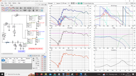
Try this filter. Not recommending it, but curious if my attempt to raise the top end works. I'm using different files.
The resistor might get very hot. I have no way to sim that. Probably OK at modest power, but really don't know. I was just playing with this as a mental exercise. The attempt was to create a more level response, without the downward slope on the top end. I can't make the tweeter go any louder but I can reduce the mid-range.
The resistor might get very hot. I have no way to sim that. Probably OK at modest power, but really don't know. I was just playing with this as a mental exercise. The attempt was to create a more level response, without the downward slope on the top end. I can't make the tweeter go any louder but I can reduce the mid-range.
Attachments
Last edited:
Have you test it ? any comment´s on it?
I feel with age and learning, that best for me is to try to "get good" on one program, so you learn WHAT it shows you
My brain isen´t like it use to be
Will do temp25 🙂Try this filter. Not recommending it, but curious if my attempt to raise the top end works. I'm using different files.
The resistor might get very hot. I have no way to sim that. Probably OK at modest power, but really don't know. I was just playing with this as a mental exercise. The attempt was to create a more level response, without the downward slope on the top end. I can't make the tweeter go any louder but I can reduce the mid-range.
I have a few 50 watts resistors!
I come back to you!
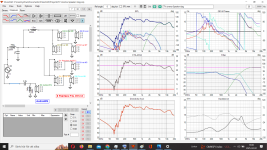
Here it is and also resistors values on 70 w rmsTry this filter
Attachments
It works and will produce a much better result than what has been presented here so far I would guess.That would take all the fun out of it if it worked.
//
As your x,y,z values (position on baffle) are all zero for all drivers it means that all nine drivers has been in one and the same location which is impossible of course but would have been really good if it was possible. So simulation is all but correct I guess...Here it is and
//
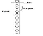
I would like to learn that x,y,z function.As your x,y,z values (position on baffle) are all zero for all drivers it means that all nine drivers has been in one and the same location which is impossible of course but would have been really good if it was possible.
Do i begain with the highest mounted driver, and go downwards?
So highest mounted driver in mm from center of cone up to the top of cabinette? (X)
Then highest mounted driver in mm center of cone to left ending of cabinette? (Y)
But the Z- plane, is that center of cone and in mm to the back of the cabinette? (Z)
Do you have a schetch for it?
Attachments
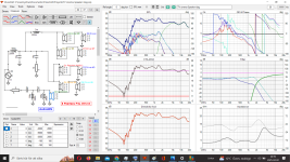
Thanks for running my last sim. I thought I had the response with less tilt, but it's about the same.
The xyz values are used to compensate for the different driver distances to the mic. The software recalculates those distances if you raise the mic, so it can calculate changes in response that would occur there.
So, with a traditional 3-way for example, you could have a nice response on axis, and confirm that it stays nice ten or fifteen degrees upwards. At some angle the drivers don't add well, and actually cancel, producing nulls.
The software should define the relative numbers. I use PCD. I think it defines the tweeter as the zero reference location vertically.
The x value would be zero for all, unless a driver is offset to the side , like when a tweeter on a 10" wide baffle, is 4" from one side, and 6" from the other. The offset would be 1".
The z offset would be like for a very deep wave-guide, as compared to a typical dome. Or a 12" woofer where the voice coil is deep into the box, but the mid is only a few inches. These locations are supposed to be the acoustic center, and often you can guess at them. Some measurement technics may actually measure them.
I don't know the curve radius of your speaker, but I assume that when you measure, the woofers are all close to the same distance from the mic. Small differences make little, to no difference at low frequencies.
Last edited:
Do you plan to try your last couple of x-overs?
When I make a x-over, it's external, and connected with jumpers. I experiment a lot, and listen for several hours before changes. Sometimes for several weeks, or months. Eventually I pick one.
When I make a x-over, it's external, and connected with jumpers. I experiment a lot, and listen for several hours before changes. Sometimes for several weeks, or months. Eventually I pick one.
By " all but correct I guess", are you suggesting it's close, or way off.As your x,y,z values (position on baffle) are all zero for all drivers it means that all nine drivers has been in one and the same location which is impossible of course but would have been really good if it was possible. So simulation is all but correct I guess...
//
- Home
- Loudspeakers
- Multi-Way
- Linesource measurements and xoverbuilding