H
HAYK
Thank you for the encouragement.
Many see impossible task to keep the bias current invariable with temperature using 50m ohm emitter resistors. To give a comparison, consider 3 pairs of outputs with 0.2 ohm resistors, biased in total 150ma. Each pair has 50ma bias gives 20mv bias voltage emitter to emitter. The Vbe must compensate the output, the driver on heatsink temperature plus the predriver in casing temperature plus a precise 20mv constant voltage, all this just by following the heatsink temperature to compensate more than 50°C junction excursion.
Here I have 200ma in 2x 0.05 ohm which is also 20mv, the Vbe is mounted upon one driver maybe a PTC on the other to follow not more than 13°C junction excursion and this, by using a small heatsink.
,
H
HAYK
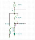
Here is a Vbe bias susptible to function with high precision. The BD transistors are identical to the drivers and mounted upon them. The Vas current is divided by an adjustable constant current to pass through the diodes the required current to bias as the drivers will mimic the same current. The 2 ohm is the resistor that gives the fix 20mv for the emitter resistors. This way the thermal drift is adjusted precisely.
R3 adjusts the bias current

R3 adjusts the bias current
H
HAYK
H
HAYK
Understanding the cFp, F as feedback. I showed that the CFP current driven it is just two transistors in cascade. The question is how much source impedance is needed to get the feedback operating. A significant value is the reflected impedance of the load which is 80kohm. Bellow is with 1M ohm driven with 200ua triangular pulse, 80kohm with 600ua and 40kohm driven with 1ma. To note that the open loop output impedance becomes 8 and 4 ohms.


Last edited by a moderator:
H
HAYK
Incredible how you are so fast. Thank you for posting your, circuit very interesting.
For what purpose is the germanium diode in the Vbe?
The 5ma current source, how it decreases the current 20ua/°C, to my opinion, one of the diodes should be glued upon the TTC and the other upon one of the outputs. The 5ma pre_bias adjusted with the base resistor.
For what purpose is the germanium diode in the Vbe?
The 5ma current source, how it decreases the current 20ua/°C, to my opinion, one of the diodes should be glued upon the TTC and the other upon one of the outputs. The 5ma pre_bias adjusted with the base resistor.
Try temperature simulation with that diode and without.
When temperature of drivers changes from 20 to 60 degrees,
a) without diode, idle current with increase by approx 15%
b) with Ge diode, it will increase only 5%
c) with Si diode it will actually decrease by double digits %
The Vbe multiplier circuit with 2 transistors for CFP, comes from D. Self book (page 532/533, 6th edition, figures 22.31 and 22.33),
but addition of the Ge diode was simpler than creating voltage reference that D. Self used.
I guess he had to do it more complicated way because he used Si diode, but 1N34A is easily
obtainable and allows to simplify the circuit.
Judging from my sims, it looks like this amp performs very similar to EF equivalent, but it's way more
stable in the wider range of conditions. In the EF version you change 1pF here or there, and it oscillates, but the CFP version
seems to not care at all 🙂
Last edited:

H
HAYK
H
HAYK
I am dealing only with the output stage for now. I will run it as unity gain follower and listen the sound.
I'll start a new thread for the complete amp.
I'll start a new thread for the complete amp.
H
HAYK
As the name CFP says feedback, it has damping and speed. With CFPs the output switches on fast by the driver but off only by the base resistor. It is necessary that both are equal to reduce the overlap shoot through current and has good damping. The goodness of bootstrapping, the resistor between Vbe and bootstrap capacitor adjusts the current gain of the CFP as well as damper as in ac it shunts the output to the bases. Bellow is with 3.3k and snubber to result best symmetrical rise and fall and damped.
Last edited by a moderator:
Proof of concept: a charge pump with a transformer can speed up turn off by pulling out charge. The transformer needs to invert the output and an centre tapped choke can do this. The inductance needs to be enough so magnetising current is less than the pull-out current, eg 20mApk of magnetising current at 50kHz for 40mApk pull-out current. And the core large enough for about 4Vpk at 50kHz. Winding resistance can be relatively large at 10 ohms so small wire is OK. I haven't tried winding a core. Maybe a small toroidal ferrite or powdered iron core that will easily fit on the main PCB.I find the concept very interesting: it is extremely simple and highly effective, unlike many similar "keep-alive" schemes.
...
It would be nice to have the complement: this fix addresses the conduction issues, but the turnoff can also be problematic especially with BJT's [emphasis added]. With a darlington output, a coupling of the bases with a 1µF helps the turnoff, but in a CFP it is more complicated [emphasis added].
I have even tried small transformers to cross-couple the bases, but it didn't work satisfactorily.
Anyway, your scheme is a worthwhile innovation, bravo for that!
The plot shows with and without the charge pull-out. at 50kHz. The crossover current is reduced from 500mA to normal (LF 250mA). Note: R19, C10 are different for the NPN power transistor since it has less charge storage than the PNP.
The amp is now safe if it oscillates at 50kHz or 100kHz. Above 100kHz slew-rate limiting occurs, so it can't melt down with this mod. It is now comparable to the Darlington output stage with its inter-base speed up capacitor.
BTW These output transistors are not "fast" (only 5MHz) so this CFP above 20kHz and without this mod can cause overheating, eg, if it oscillates at 50kHz or above. But with a faster output stage the input filter is not necessary to stop overheating.
Without a faster output stage it isn't practical to limit the amp to 20kHz by using an input filter IMO (because the slew rate becomes too low).
Also included are 1) replacing the transformer with an opamp (60mApk at 6V), and 2) a discrete version.
Cheers, IanH
Attachments
H
HAYK
I was trying to discharge one output by the others driver, it didn't work well. When I saw your diodes to discharge through accidentally one diode got shorted by error and this is the result running at 100khz. If you delete the 0 ohm resistors, there is only two diodes and one capacitor added.
Thank you for your ingenious idea to get the output current info from the derivative of the voltage. I will simulate with my simpler circuit.

Thank you for your ingenious idea to get the output current info from the derivative of the voltage. I will simulate with my simpler circuit.
Interesting propositions: Hayk's solution might cope better with reactive loads, but it will have a negative effect on the PSRR
The circuit below eliminates the transformer:


The base emitter resistors can be doubled and the keep-on current halved.
The amount of charge pull-out does depend on the load resistance - with 16 ohms the crossover current is halved. An inductive component in the load seems to have less effect.
Maybe sending the derivative of the output current (as well as at present the derivative of the output voltage) will allow the charge pull-out to be more correct for higher load impedances?
But I don't think it matters much if the crossover current drops (below the normal LF level) with ultrasonic signals - the main concern is that the amp doesn't overheat due to high cross conduction if/when it goes into oscillation for an extended time.
Attachments
H
HAYK
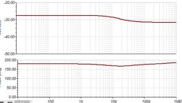
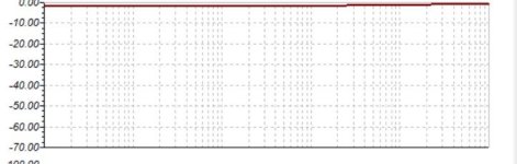
I tested the PSRR with and without 100nF, it looks that with has better PSRR at high frequencies. May be the driver which is feedbacking the input rejecting the supply ripples. It is not dependant to the source impedance. Bellow is with and without 100nF with 0 ohm source and 14k.

Attachments

Last edited by a moderator:
H
HAYK
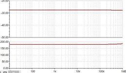
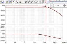
The frequency response of a CFP is a mediocrity compared to 2_3EF. If the later swims in Mhz domain, the CFP hardly reaches the 200khz. To note that in standard design, the VAS carries the dominant pole and the second pole is that of the output. With CFP, the design needs a different gain/pole distribution. Bellow is measured with 14kohm source which could be that of the VAS + bootstrap.
Attachments
Hayk,
I don't think the lower CFP speed compared to the 2_3EF is really a problem because it's full-power bandwidth that's important - and this is limited by the slew-rate which is determined mainly by the dominant pole. In your amp full-power BW is about 100kHz - SR about 10V/us. If it is to drive capacitive loads up to say 50nF (most likely from typical cable capacitance) and a typical 1uH output inductor then the compensation capacitor needs to be increased to 150pF and 8V/us SR (sims attached).
Here's an updated version with current derived charge pull-out - yes you are right - it's the way to go 🙂 :

The output current derivative is sensed by adding a secondary to the output inductor - eg 1/4 dia. bifilar is easily done. It can do 100kHz safely and now tracks load changes!👍 Sinewave 50kHz shown below at 8 and 16 ohms:

and a square wave

With a square wave for 20V output, not clipping, and with a 50nF capacitor across the 8/16R loads it oscillated at around MHz with the 100pF compensation. So the compensation was increased as mentioned. This squarewave is harsh test for the charge pull-out circuit because it is operating at the slew-rate limit. But still the dissipation due to crossover is controlled enough to not cause overheating long term - so it appears it work OK with different waveforms.
So I'd be happy to use this approach in my amp. It's free for any or all.
Cheers, IanH
I don't think the lower CFP speed compared to the 2_3EF is really a problem because it's full-power bandwidth that's important - and this is limited by the slew-rate which is determined mainly by the dominant pole. In your amp full-power BW is about 100kHz - SR about 10V/us. If it is to drive capacitive loads up to say 50nF (most likely from typical cable capacitance) and a typical 1uH output inductor then the compensation capacitor needs to be increased to 150pF and 8V/us SR (sims attached).
Here's an updated version with current derived charge pull-out - yes you are right - it's the way to go 🙂 :
The output current derivative is sensed by adding a secondary to the output inductor - eg 1/4 dia. bifilar is easily done. It can do 100kHz safely and now tracks load changes!👍 Sinewave 50kHz shown below at 8 and 16 ohms:
and a square wave
With a square wave for 20V output, not clipping, and with a 50nF capacitor across the 8/16R loads it oscillated at around MHz with the 100pF compensation. So the compensation was increased as mentioned. This squarewave is harsh test for the charge pull-out circuit because it is operating at the slew-rate limit. But still the dissipation due to crossover is controlled enough to not cause overheating long term - so it appears it work OK with different waveforms.
So I'd be happy to use this approach in my amp. It's free for any or all.
Cheers, IanH
Attachments
H
HAYK

Clever arrangement. A bifilar secondary winding could be used to eliminate possible PSRR issuesThe output current derivative is sensed by adding a secondary to the output inductor - eg 1/4 dia. bifilar is easily done. It can do 100kHz safely and now tracks load changes!
- Home
- Amplifiers
- Solid State
- Linearizing the CFP crossover - P3a of Rod Elliot as example