Hi Ian,
I the sim in post #58, you have the output devices biased at 250ma. Isn't 25ma to 75ma more common? Why the higher value? Is it the changes that allow it to run higher and have a greater class A region?
I the sim in post #58, you have the output devices biased at 250ma. Isn't 25ma to 75ma more common? Why the higher value? Is it the changes that allow it to run higher and have a greater class A region?
H
HAYK
I took back the OPS into consideration, I took off the diodes as they were causing higher distortion, and just increased the mutual capacitor to 220nF. With 100nF, the NPN was perfect but why not the PNP. I tried njw ones, the same PNP problem although they have the same Cob. For me just adding a capacitor resolves the cross switching problem. The only harm I see is at start up, it will short rail to rail the time it charges.
Bellow is 100khz.
Bellow is 100khz.
Attachments

H
HAYK
The performance of this OPS depends upon the source impedance, for that I started an amplifier using it to follow on The Blamless CFP.
https://www.diyaudio.com/community/threads/the-blamless-cfp.402614/#post-7436744
https://www.diyaudio.com/community/threads/the-blamless-cfp.402614/#post-7436744
H
HAYK
As the source impedance of The Blamless CPF is only 4 ohms, the bias circuit should be much lower so that the upper and lower branches see equal and low impedance. I modified the last on #43 with Germanium diode in Minek way and CFP the current regulator, the result is 1.45 ohm.

@brian92fs, it was Hayk who started this thread. I hope he doesn't mind me answering your query #61. It is a lower than usual emitter resistance of 50 milliohms that requires the higher bias current to get minimal crossover distortion. In this CFP it's about 10mV across each resistor.I took back the OPS into consideration, I took off the diodes as they were causing higher distortion, and just increased the mutual capacitor to 220nF. With 100nF, the NPN was perfect but why not the PNP. I tried njw ones, the same PNP problem although they have the same Cob. For me just adding a capacitor resolves the cross switching problem. ...
Hayk,
The mjl21193C PNP has a larger CJE of 13e-9 compared to 8e-9 for the NPN mjl21194C (but as you note the CJC's are about the same). This makes it tricky to get both NPN and PNP right with a common capacitor between the NPN-PNP bases.
I had used that method before here https://www.diyaudio.com/forums/sol...-cross-conduction-distortion-post5068725.html but it was with a CFP without the feedback. It should be OK on a CFP. My simplified circuit is here where the R &Cd values can be tweaked independently for the NPN and PNP power transistor differences.
H
HAYK
The main acting capacitor is the Cob which gets multiplied by the voltage gain hence the gm. For Motorola power transistors, the complimentary have the same Cob 400p_600p. Maybe the models have different gms.
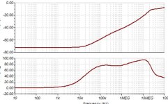
I tested again the PSRR with and without 220nF, indeed with, starts getting bad from 100Hz, so, acceptable.This is measured with 4 ohms source, the precedent was 14k.

I tested again the PSRR with and without 220nF, indeed with, starts getting bad from 100Hz, so, acceptable.This is measured with 4 ohms source, the precedent was 14k.
Attachments
Last edited by a moderator:
H
HAYK
I switched to LT but I have a problem with 2N7000. I have two models from Onsemi and Fairchild.Lib both are not recognized by LT. In the compo.lib I included both, if someone can make it work.I made a mistake measuring the source impedance, 4 ohm, it was closed loop in open loop it is 120 ohm. So I changed the circuit and got now 12 ohm. I decreased the nested feedback 6db and now it is 24 ohm sufficient to result 0.03% THD with degrading harmonics. There is more 40db NFB to apply in closed loop. I will use the Vbe CFP Minek way but thermally an NTC with be in charge as in post 16.
With this platform I can more precisely adjust the pre_bias 5ma, already it is very linear.
This is in closed loop with 2Ap applied on the output. It measured 1mohm or DF of 8000.
View attachment 1207491
Attachments
H
HAYK
Thank you for adjusting but the 2n7000 is still not recognized.
The Toshiba spice models for C5200 and A1943 have the same problems.
The Toshiba spice models for C5200 and A1943 have the same problems.
Further fix to your P3B.asc circuit - it needs Q3 with an NPN model. You have an NPN symbol with a PNP model. (LT doesn't flag it as an error!)
For Q3 I used 2SD669A. It carries 45mA. Is that what you want? Maybe R12 to 47 ohms gives 22mA, then R22 1k2 for 200mA in output trs. Good to go.
--------------
I just read your post after uploading the above. Which LT version are you running? I am using the older LT-IV and it runs after above NPN change. I don't have LT-XVII here but can run it tomorrow.
Alternatively, do you want me to post the file I have running now using LT-IV?
Last edited:
H
HAYK
Thank you for your help. Once I replaced the 2n7000 with k170 it started working so I could see the errors. I copied it from Tina working circuit , it is different. I see about it tomorrow. I have version 17.
H
HAYK
Hayk,
My file that worked on LT-IV has now been run on LT-XVII (ver 17) - it doesn't like 2N7000 in your models.
So I used 2N7000b (b is for Bordodynov) and it runs error free on LT-17.
Also with LT-17 I get a similar OL THD as you got with mjl1302C or mjl21193C using your model file. (My sim used 20Vpk with 10mVpk in, and 260mA with mjl21193C and 310mA with mjl1302C, and 22mA in Q3)
My file that worked on LT-IV has now been run on LT-XVII (ver 17) - it doesn't like 2N7000 in your models.
So I used 2N7000b (b is for Bordodynov) and it runs error free on LT-17.
.model 2N7000b VDMOS(Rg=3 (Lambda=1m Vto=1.6 Rd=0 Rs=.75 Rb=.14 Kp=.17 mtriode=1.25 Cgdmax=80p Cgdmin=12p Cgs=50p Cjo=50p Is=.04p ksubthres=0.1 mfg=Fairchild Vds=60 Ron=2 Qg=1.5n)Also with LT-17 I get a similar OL THD as you got with mjl1302C or mjl21193C using your model file. (My sim used 20Vpk with 10mVpk in, and 260mA with mjl21193C and 310mA with mjl1302C, and 22mA in Q3)
H
HAYK
AAh finally, a working model. Thank you.
Now that I can adjust in open loop mode, I increased the emitter resistors to 0.1 ohms to get more current feedback. The question now is how much pre_bias is needed. With 50ma and 218ma in total for non complementary paire njw0281 and njw1302 on Tina I have this.

With LT using always Onsemi models I need less than 200ma bias to get this.

Note that it became non_switching.
Now that I can adjust in open loop mode, I increased the emitter resistors to 0.1 ohms to get more current feedback. The question now is how much pre_bias is needed. With 50ma and 218ma in total for non complementary paire njw0281 and njw1302 on Tina I have this.
With LT using always Onsemi models I need less than 200ma bias to get this.
Note that it became non_switching.

H
HAYK
I tried combination of output transistors as the purpose is to get beautiful sound rather precise kind. The mismatch is very important to generate even harmonics and kill the monotonicity of the odd ones. The best combination I got is njw0282 and 1302 . To get continously decreasing harmonics the output required to be driven at very low impedance as I had to increase by 4 fold the nested NFB to be about 6 ohms. The loop gain was 40db now is decreased by 12db to be 28db only. In closed loop the THD is less than 0.002% but Ideal spectrum.

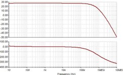
The frequency response is bellow. The I put capacitor 330pf limits.
The frequency response is bellow. The I put capacitor 330pf limits.
Attachments
Last edited by a moderator:
H
HAYK
If look the phase of the second harmonic, it is opposite. This type of amp will make the sound soothing making less horn type, backwards in staging. Tomorrow I will do it in phase to make it forward.
Not sure I understand what this means. I don't see any 330p caps in the schematic.The I put capacitor 330pf limits.
When doing this in simulation, it seems this would be very dependent on the models you are using as opposed to the actual devices themselves. I suspect this would be better tuned on the bench with real devices.I tried combination of output transistors as the purpose is to get beautiful sound rather precise kind. The mismatch is very important to generate even harmonics and kill the monotonicity of the odd ones. The best combination I got is njw0282 and 1302 .
What are the AM1, AM2 and AM3 devices?
Do you have an alternative for 2SD669/2SB649 since these have been unavailable for many years now?
How do you plan to implement the current source?
What is inductor L1 for? It appears to have a value of zero assigned to it.
T8 also looks to be wrong. You have the NPN BC337 designated for a PNP device... I think - the labels on the schematic are overlapping making it difficult to read.
H
HAYK
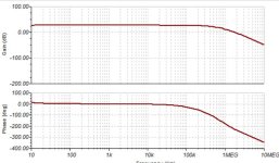
The input filter capacitor 390pf is C5 it is at the input shunting R15 1k ohm, bellow Bode is without. The C4,150pf is to cut above 20khz entering the Amp.
B649,D669 are manufactured see post 36 and as HSB649,HSD669. Onsemi has similar ksa1220,ksc2690.
AM1,2,3 are current probes.
The current source is on post 6 but made with DN2540.
The inductors is to make it run in open loop while output DC is in closed loop.
The mismatch of the transistors is a matter of early not Hfe. The PNP transistors have lower early than the complimentary NPN. Because of this the current gain decreases more with PNP when it's Vce voltage decrease while the Ic increases. The result, in EF the positive part of the signal gets more amplified than the negative and inversely in CFP. Maybe that what CFP has a different sound. Remark that if you feed the Amp with inverted signal and invert the speaker wires you get the opposite in both cases.
Attachments
Last edited by a moderator:
- Home
- Amplifiers
- Solid State
- Linearizing the CFP crossover - P3a of Rod Elliot as example