From a practical standpoint I can tell you that when I currently run my audio out of the interface at 600ohm and into the transformer at 600ohm, then out of the transformer again at 600ohm and back into the interface which has a resistance of 10k, I do not observe any low end attenuation. I do notice an overall signal attenuation of about half a db, but that's actually what the 111c is rated for.Hmmmm.
I'm still trying to wrap my head around using transformers myself, but I don't think 600R is ideal if the secondary is loaded with 600R. That would cause the low end response to be down -3dB I think. The source output impedance should be at least 10x lower(?). I'll let the pros weigh in on that one though.
When you say "out of the transformer again at 600ohm", are you actually loading the secondary with a resistor? A transformer doesn't have an impedance of it's own. If the 10k of the interface is the only load on the secondary, then that's what source on the input sees.
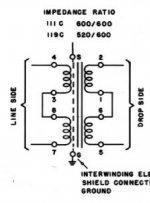
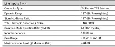
Yeah I guess I'm a bit out of my depth here. All I know is it's wired in the 1:1 600 ohms configuration, like in this picture, and that input impedance of my balanced interface is 10kohms. I also included the input specs of my interface.When you say "out of the transformer again at 600ohm", are you actually loading the secondary with a resistor? A transformer doesn't have an impedance of it's own. If the 10k of the interface is the only load on the secondary, then that's what source on the input sees.
Attachments
Last edited:
A 1:1 transformer just reflects impedance from input to output and vice versa, unchanged. There is no 600 ohms in the equation here unless that happens to be the output impedance of the compressor.Yeah I guess I'm a bit out of my depth here. All I know is it's wired in the 1:1 600 ohms configuration, like in this picture
Just think of the load the source sees, and source impedance the load sees, as being the same as if the transformer wasn't even there.
Exactly. Just to add...when a transformer is specified as having a primary or secondary at a particular impedance, that means it's optimized to work at that impedance, not that it IS that impedance.A 1:1 transformer just reflects impedance from input to output and vice versa, unchanged. There is no 600 ohms in the equation here unless that happens to be the output impedance of the compressor.
Just think of the load the source sees, and source impedance the load sees, as being the same as if the transformer wasn't even there.
The balanced signal comes out of my interface at 600ohms, and I believe it remains that way out of the compressor.. I don't have specs on it because it was a clone built by a guy. All I know is that the output transformer of the SSL is a 1:1 JT-11-DMCF.A 1:1 transformer just reflects impedance from input to output and vice versa, unchanged. There is no 600 ohms in the equation here unless that happens to be the output impedance of the compressor.
Just think of the load the source sees, and source impedance the load sees, as being the same as if the transformer wasn't even there.
Also, I may not use the compressor once I have an amp that can drive the 111C, so it would just be coming out of the interface at 600ohms. But, I may end up mixing and matching. I have a patchbay so I can change the arrangement of these units on the fly.
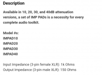
One last thing is that I have -30db pads after the 111C before it goes back into the interface. The pads actually bring it down to 150ohms. I'm not opposed to changing those though. I only got them bc they were fast and cheap.
Good to know. Thanks for clarifyingExactly. Just to add...when a transformer is specified as having a primary or secondary at a particular impedance, that means it's optimized to work at that impedance, not that it IS that impedance.
So let's assume the output of the interface is 600ohms and goes into the transformer and then goes back into the interface that has 10k ohm input. Does that still mean the secondary of the transformer is 600ohm? Or does that become 10k because that's the impedance of the input it's going into? I was looking at ohms as a directional thing.. so because the input of the transformer was seeing 600, and it's wired for 1:1, that the output also is 600, and then gets converted to 10k after if goes into the interface, which then is converted to a digital signal...A 1:1 transformer just reflects impedance from input to output and vice versa, unchanged. There is no 600 ohms in the equation here unless that happens to be the output impedance of the compressor.
Just think of the load the source sees, and source impedance the load sees, as being the same as if the transformer wasn't even there.
Right, I forgot about the pads. From what I can find online (I'm not familiar with this at all), it looks like the pad in parallel with the 10k of the interface would present a 4.55k load to the transformer.One last thing is that I have -30db pads after the 111C before it goes back into the interface. The pads actually bring it down to 150ohms. I'm not opposed to changing those though. I only got them bc they were fast and cheap.
EDIT: Scratch that; I don't know if a 150Ω mic pad is symmetrical in/out (H-pad).
Last edited:
Looks to be 1kRight, I forgot about the pads. From what I can find online (I'm not familiar with this at all), it looks like the pad in parallel with the 10k of the interface would present a 4.55k load to the transformer.
EDIT: Scratch that; I don't know if a 150Ω mic pad is symmetrical in/out (H-pad).
Attachments
But its all one chain.. how is the load on the transformer not simply the the resistance that it is going into? In this case 1k.. it's not like the transformer output is split into two cables, one going directly into the interface and the other going into the pad...So parallel with the 10k of the interface would be around a 909Ω load on the transformer.
That's just how it works. The transformer sees the pad in parallel with the input of what the pad is connected to. Not a big deal, I was just trying to get to the bottom of what the actual load on the transformer is.
Don't feel bad, a lot of this stuff is a struggle for me too, which is pretty embarrassing considering I joined this forum 18 years ago.Damn I have a lot to learn
I find this calculator to be absolutely worth the 5$... There is also a free version. I've lost count of how many times I've used it 🙂
https://play.google.com/store/apps/details?id=it.android.demi.elettronica.pro&hl=en_CA&gl=US
https://play.google.com/store/apps/details?id=it.android.demi.elettronica.pro&hl=en_CA&gl=US
It will be closer to 1 kohm than you think. The pad has to consist of at least three or four resistors and the 10 kohm is only in parallel with one or two of them.So parallel with the 10k of the interface would be around a 909Ω load on the transformer.
You're right. I found the specs for the specific pads and it says they're H-pad type. Using an online calculator for 1k input and 150R output @ -30dB, and then simulating it with 10k in parallel with the output, I get 1.01k input impedance.It will be closer to 1 kohm than you think. The pad has to consist of at least three or four resistors and the 10 kohm is only in parallel with one or two of them.

FYI I have a multimeter so if you want me to take any kind of measurements I can. I can use music or my music production software can generate any kind of tone/wave.You're right. I found the specs for the specific pads and it says they're H-pad type. Using an online calculator for 1k input and 150R output @ -30dB, and then simulating it with 10k in parallel with the output, I get 1.01k input impedance.
New thoughts, may have been mentioned. Transformer distortion results from core saturation which is caused by current not voltage. This means you need a large load (at least 600 ohms) to get lots of current and a source that can provide it. Once there you can probably adjust the amount of distortion by varying the load.
- Home
- Source & Line
- Analog Line Level
- Line Amp Capable of +35dbu