
Good question:B) Which belt are you using and where did you get it from?
- good one, tight, is from generic electronic store, guaranteed made in PRC
- loose, funny ones are from HIFI audio store, don't remember the brand
Dont know, yet.that 0.5sec period chart looks super clean and regular. what is your ratio of platter to pulley size?
it could be some travel procession of the platter bearing. I have seen a fine line between how smooth a platter bearing is vs how tight the bearing sleeve tolerance is.
On the good belt graph you see just random "hair" of noise which is quite normal on all TT's and at this one very small.
Then I just change belt, and get very precise 0.5 sec intervals.
Pulley ratio is about 13.8, so suspected times are 1.8 sec (platter 1 turn) 0.13 s (one motor turn) and 0.016 s (8 pole pairs in motor)..... 0.5s +- doesn't fit anywhere, even close.
I think if it is to bearing it would show it with any belt.
Nothing to be sorry about. I invested so much time in making TT that few hours more dont mean much, at least we made small progress in understanding performance results of surface treated pulley...That looks very regular in #317. You know the picture I mean; that must be trying to tell you something. Other than that, looks like the drain cleaner isn't such a good idea after all. Sorry about that.
Is it simply an undamped oscillation set up by compliance of the belt and mass of the platter? Agreed, something has been learned about pulley surface finish. Just not sure what.
By the way, my plan for (VHS) capstan motor having slimmer shaft and only a sleeve bearing below is to replace the shaft with a 4mm shaft taken from a floppy drive, fit pulley on shaft and machine it in place (this assumes I can get the shaft concentric in the lathe). I also intend to fit lignum vitae sleeve bearings (salvaged from old lawn bowls) at each end of the shaft. This will make for a slightly awkward support structure above and below the motor, a little like the idler support for a Garrard 301, but I don't mind.
By the way, my plan for (VHS) capstan motor having slimmer shaft and only a sleeve bearing below is to replace the shaft with a 4mm shaft taken from a floppy drive, fit pulley on shaft and machine it in place (this assumes I can get the shaft concentric in the lathe). I also intend to fit lignum vitae sleeve bearings (salvaged from old lawn bowls) at each end of the shaft. This will make for a slightly awkward support structure above and below the motor, a little like the idler support for a Garrard 301, but I don't mind.
That could be explanation. For me at the end doesnt matter much as with different belt it is completely different picture.Is it simply an undamped oscillation set up by compliance of the belt and mass of the platter? Agreed, something has been learned about pulley surface finish. Just not sure wha
we learned at least that it doesnt help to etch, not like this anyway 🙂
I really envy you for having lathe at home!
Can you make a sketch what you plan to do? 2 slot-less motors from beta-cams (one is in #308) already have 5mm shafts, but ball bearings need to be changed for bushings, might be a suggestion?
btw, are you measuring speed with a record on, and the needle on the record?
that tiny little bit of stylus drag is meaningful, and you will likely see even better numbers. my platter is about 6kg, and I still see WOW go from 0.1% to about 0.05% when the needle is down.
anyway, once you are in the speed variation less than +/- 0.1% and WoW around 0.05%, it is pretty darn good!
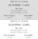
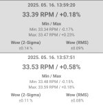
I don't trust this rotating smartphone measurement principle. If you place the phone off-centre, the angular velocity of the sensor fluctuates within a revolution. See my measurements, the first is about centered, the second is close to the platter edge. It is impossible to perfectly centering, and the position of the gyroscope within the smarthone is unknown. I suppose it should be placed right on top of the spindle.
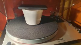
I used an ice cream bowl with a hole in the bottom.
I used an ice cream bowl with a hole in the bottom.
Attachments
Thanks Jayme, yes, I also think it is wonderful. Now im just touching some in depth details, but very happy with what it is, repeatable WOW under 0.05%, reaching 0.02 is fantastic, particularity for belt drive.btw, are you measuring speed with a record on, and the needle on the record?
that tiny little bit of stylus drag is meaningful, and you will likely see even better numbers. my platter is about 6kg, and I still see WOW go from 0.1% to about 0.05% when the needle is down.
anyway, once you are in the speed variation less than +/- 0.1% and WoW around 0.05%, it is pretty darn good!
All latest measurements are without LP, I was trying and could not measure any meaningful difference between needle on the record and in the air, posted that in #267.
My platter is similar weight, 6,5 kg, but I don't know how the rest of your player is designed.
Hi Laszlo,I don't trust this rotating smartphone measurement principle
At beginning I was also skeptical, but more I use it, more I trust it and like it.
I get all the same measurements regardless of phone position on the platter, within 0.01% which is threshold, tried that several times. Dont know why you get different depending on position, and such big one....
In post #253 I showed 2 different phones measuring at same time, results pretty close.
By the way, roll of masking tape or duct tape makes better stand for phone 🙂
I don't know if it is against the forum rule to cite this discussion:
https://audiokarma.org/forums/index.php?threads/thorens-td160-wow-flutter.1007607/
https://audiokarma.org/forums/index.php?threads/thorens-td160-wow-flutter.1007607/
Perhaps because of asymmetric load on the platter.Dont know why you get different depending on position, and such big one....
Hi, I don't think it is not allowed to post links, I do it all the time
On my platter it will not (and does not) make difference... On what TT did you put it? I did not really on very light platter TT's
By the way, forgot to mention, this app doesn't measure average speed accurately. Speed needs to be measured by something else, and than phone calibrated accordingly. After that everything is perfect.
Szia,
I quickly took 2 measurements on my TT, 3 different phone positions: on reel in center, near spindle and 90deg to spindle... All 3 measurements are the same.
Last week I measured Revox B795, fantastic tt, 0.03% without service, 2 kg platter and same in all directions of the phone.
Than just for fun I took out old BSR TT that I want to make for my 9yo son to play with. This TT is super light platter and wasn't serviced in decades. On this one, WOW goes from 0.17% (in center) to 0.57% 90 deg to spindle. Interesting...
Doesn't really need a sketch (which is difficult for me to get into computer). I have in mind two lignum vitae sleeves bored to be as tight as tolerable without excessive friction, one sleeve at the top, one on the bottom. Pulley would be below upper sleeve. Each sleeve would be mounted centrally in a large disc. The discs would be larger than the motor's periphery, allowing three rods to bolt lower disc to upper. To take the weight of the rotating mass, a neodymium magnet on the bottom of the protruding shaft facing an opposing neodymium magnet whose height can be adjusted, probably on a screw thread. That way, we get a noiseless support. Obviously, the awkward bit is that the belt must be fitted before the motor is assembled...Can you make a sketch what you plan to do? 2 slot-less motors from beta-cams (one is in #308) already have 5mm shafts, but ball bearings need to be changed for bushings, might be a suggestion?
Hi, I meant just hand sketch.... Is this about what you have in mind? :

I think not being possible to quickly change belt is big issue...They are wear&tear parts..
I think not being possible to quickly change belt is big issue...They are wear&tear parts..
Yes, that's it. I might put the magnets below the bottom plate, but that's a minor detail. Changing the belt will require the three screws holding the top plate on to be undone, the top plate removed, belt changed, top plate replaced, three screws refitted. Not really a serious problem. The pillars will probably be reasonably substantial; 10-12mm diameter aluminium. Top and bottom plates 1/4" thick aluminium (I have a 6ft x 3ft sheet of the stuff!) Haven't decided about the motor plate.
I "serviced" my turntable a bit, eliminating the belt friction to the speed change lever. It is much better now. With and without needle in groove.Hi Laszlo,
At beginning I was also skeptical, but more I use it, more I trust it and like it.
I get all the same measurements regardless of phone position on the platter, within 0.01% which is threshold, tried that several times. Dont know why you get different depending on position, and such big one....
In post #253 I showed 2 different phones measuring at same time, results pretty close.
By the way, roll of masking tape or duct tape makes better stand for phone 🙂
Attachments
Excellent Laszlo,
Funny things are that even smallest changes do affect belt drive TT, and this phone app is capable of capturing them. I found it perfect for improving TT as whatever change I do, I see it immediately., keeping the same measurement setup of course.
PS, one thing I mentioned somewhere, worth to repeat; I tried to use my old Catrepilar S60 phone, it gave me just garbage. Both iPhones however (model 7 and model 11) gave me perfect and complimentary results (In no way I'm promoting Macintosh, on opposite , I'm PC and android person). In short, type of phone matters....
- Home
- Source & Line
- Analogue Source
- Limestone turntable, help needed with motor and drive