Re: Re: Re: Too less resistance
If you can increase only R1 keeping R2 at a minimum, the output impedance seen by the load (amplifier) is basically equal to R2 however high is R1, thus it's just fine for any amp.
From the point of view of the amp, R1 and R2 are in parallel... to be exact, the output impedance of the attenuator is (Zs+R1)//R2, where "Zs" is the output impedance of the source.
BTW: will you really ever need -80dB?
With reasonable amounts of gain in the chain, attenuation up to some -40dB is usually more than enough to get all the listening levels that you may need in practice. At -60dB what you get is likely no more than a whisper, if you can hear anything at all. At -80dB it's just plain mute. 😀
Originally posted by Tolu
The main problem is that the lowest resistance is about 25 Ohms. To receive the same effect like a 10k pot (-80dB), the value of R1 has to increase to about 250k. But then your impedance for most amps is very high!
If you can increase only R1 keeping R2 at a minimum, the output impedance seen by the load (amplifier) is basically equal to R2 however high is R1, thus it's just fine for any amp.
From the point of view of the amp, R1 and R2 are in parallel... to be exact, the output impedance of the attenuator is (Zs+R1)//R2, where "Zs" is the output impedance of the source.
BTW: will you really ever need -80dB?
With reasonable amounts of gain in the chain, attenuation up to some -40dB is usually more than enough to get all the listening levels that you may need in practice. At -60dB what you get is likely no more than a whisper, if you can hear anything at all. At -80dB it's just plain mute. 😀
Re: Too less resistance
If you only drive a mono attenuator the voltage drop on the pot is nearly halved, so it will drive the leds with more current.
Using the pot with a stereo attenuator you should have higher impedances.
Cheers
Andrea
Tolu said:Hi
I soldered a 100k log pot and 100 Ohm R between V+ and LED+.
I tested with 0 Ohm (~25 Ohm LDR), 18.6 kOhm (~426-528Ohm LDR after 2 minutes) and 92.5 kOhm (~1.9 - 2.64 kOhm LDR).
But with 95 kOhm (max of the pot) I got 3.3 kOhm. How will I simulate a 10k pot with the Lightspeed mkII circuit if the max. LDR resistance is only 3.3 kOhm???
Regards
Thomas
If you only drive a mono attenuator the voltage drop on the pot is nearly halved, so it will drive the leds with more current.
Using the pot with a stereo attenuator you should have higher impedances.
Cheers
Andrea
Re: Re: Re: Too less resistance
Anyone needing 80db of attenuation has far too much system gain.
Tolu said:The main problem is that the lowest resistance is about 25 Ohms. To receive the same effect like a 10k pot (-80dB), the value of R1 has to increase to about 250k.
Anyone needing 80db of attenuation has far too much system gain.
Re: Re: Re: Re: Too less resistance
No, I am a bat!
Thanks, for all the replies.
@George:
I think that your 100k pot is stereo and you doubled the impedance to 200k, or!? I just have a mono pot. On your circuit of mkII was only 100k log. So your highest LDR resistance will be higher than mine at 100k LED attenuation (3.3K). It would be nice if you can cofirm this and tell me what your highest LDR-resistance is at what LED-resistance.
Only to avoid any confusions about my LDR-R values, here is my measure setup:
jeff mai said:
Anyone needing 80db of attenuation has far too much system gain.
No, I am a bat!
Thanks, for all the replies.
@George:
I think that your 100k pot is stereo and you doubled the impedance to 200k, or!? I just have a mono pot. On your circuit of mkII was only 100k log. So your highest LDR resistance will be higher than mine at 100k LED attenuation (3.3K). It would be nice if you can cofirm this and tell me what your highest LDR-resistance is at what LED-resistance.
Only to avoid any confusions about my LDR-R values, here is my measure setup:
Attachments
As already said, the number of leds driven with the potmeter will influence quite a bit the minimum current flowing into them.
Since the resistance is a function of the led current....
Cheers
andrea
Since the resistance is a function of the led current....
Cheers
andrea
Thomas, to all my customers for the last 2 months I have been using single 100k log, and in use on my system they have virtually the same feel as the dual 100k log pot had, singles are easier to source and a little cheaper as well.
Cheers George
Cheers George
Attachments
@Andypairo
That's a good point which I haven't considerd.
If you drive 4 LEDs instead of one current decreases, logically!
I was just a little bit confused because in post #97 is a drawing of George with a dual pot. The later one in post #758 is just a single pot.
I think only for matching purposes it would be better to use a 200k or 1 Meg pot.
This evening I will complete it with plan mkII.
Regards
Thomas
Pot value
Thomas,
I was playing around with the power supply in mine a few days ago. It has been finished with R2 type for a few months.
It is a mono control, and I had several pots to select from. Measuring it goes from around 9k in the middle to 11K at min and max attenuation.
To get the two channels with very close measured impedance it required using pots that had different mesured resistances. The left channel measues 214K and the other 224K. This shows that my matching was either not very good, or in building I got the sorting mixed up. Try to match the two series and the two shunt as close as possible. The match between the series/shunt is not as crucial. It will just mean the the input impedance of the circuit is not the same at minimum attenuation as it is a maximum when they are not close.
If using a stereo control, a real 100K log pot will get just about where others report. 7 - 10K. If using sorted, look at the letter grade. The higher the letter, the higher the resulting impedance.
To get the resistances used in mine, I am using 250K alpha 26 mm dual log pots. Paralleling the two tracks to get a 125K control. Then measuring to see actual resistance. They are about -10 - 0% from the limited number I have measured. My old ss tuners have high output impedance and sound a little better with a 10K control.
George
Oops,
Forget the last confusing statement. The 250K dual logs pots are in the unit with R3 LDR's.
The unit with R2 type has 500K dual Alpha log. This should make a 250K single when paralled. But the all seem to mesure lower.
I was jacking around with the power supply to try and apples to apples the R3 to the R2. But have not gotten that far. Both seem to work great, just the attenuation available is higher with the R2. But only maybe another 6dB.
George
Are there distortion spectra available for the Lightspeed? From my experiments and practise with LDR cells I found that power supply noise/ripple might very easily dominate artifacts as it modulates illumination. For example, im my posted measurement I have small +-100Hz IM sidebands around the fundamental, although I used pure (dimmed) daylight to iluminate the cell. But a running lightbulb in a neighbouring flat, some 30m away, added enough modulation to show up in the 1Khz spectrum, with zoomed X-axis. It was not from direct power supply hum in the test setup, I double checked for that.
Regards, Klaus
Regards, Klaus
I am currently building my second Lightspeed, this time using a single 100k log pot and a LM317 Reg (orignal LS was dual 100K Log pot with LM7805 Reg). All LDRs are the R2 version.
After some critical listening in my UCD400/Magnepan system, it almost sounds out of phase - some music seems missing.
Bad matching of LDRs? I admit I didn't spend much time matching the slopes...nor did I do much on the second LS (lazy and busy with other things)
I am hoping the change from the dual pot and regulator may be the reason...but could bad matching cause an out of phase issue?
No. Unless you've managed to build an allpass filter by accident, which is very very unlikely to say the least. Did you check spkr polarities?john65b said:I am hoping the change from the dual pot and regulator may be the reason...but could bad matching cause an out of phase issue?
john65b said:this time using a single 100k log pot and a LM317 Reg
John,
I hope you mean 2 single log pots, not just one pot?
Bear
john65b said:
After some critical listening in my UCD400/Magnepan system, it almost sounds out of phase - some music seems missing.
Bad matching of LDRs? I admit I didn't spend much time matching the slopes...nor did I do much on the second LS (lazy and busy with other things)
john65b, bet you have bad channel imbalance at your set listening volume, a couple of members have said the same as what you have to me, "out of phase, something misssing" then I told them to reverse channels, and then they saw the light. "BAD LDR MATCHING" what they had was no central image.
Cheers George
Matching is very time intensive!
The parts are not easy to measure because in time response is a high shift in resistance. So, I measured after 2 minutes. Most of them were than stable enough.
I had 4 measure points and don't believe there is a repeatable assumption about their curve!
It's getting late so I have to continue the weekend for my lightspeed but I am now more sceptical than before because after matching is still too much variance between the couplers.
Burmester takes gold-plated reed relais and resistances. That's my next trial.
Regards
Thomas
George,
I did not try switching the channels - I will try tonight.
Bearman - thanks for the PCB board. Had to get some other projects off my desk before I could build the second lightspeed. Finally got my enclosure too. I will post a pic later this weekend if I have the opportunity...
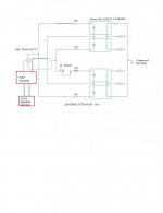
The newest schematic has a single 100k pot... +5V supply to wiper and two other leads from single pot to the LEDs...no need for a dual 100K pot anymore.
The single 100K Log Pot I have now is switched, so I can turn off the unit from the knob. Real handy.
I did not try switching the channels - I will try tonight.
Bearman - thanks for the PCB board. Had to get some other projects off my desk before I could build the second lightspeed. Finally got my enclosure too. I will post a pic later this weekend if I have the opportunity...
The newest schematic has a single 100k pot... +5V supply to wiper and two other leads from single pot to the LEDs...no need for a dual 100K pot anymore.
The single 100K Log Pot I have now is switched, so I can turn off the unit from the knob. Real handy.
Tolu QUOTE:Matching is very time intensive!
The parts are not easy to measure because in time response is a high shift in resistance. So, I measured after 2 minutes. Most of them were than stable enough.
I had 4 measure points and don't believe there is a repeatable assumption about their curve!
It's getting late so I have to continue the weekend for my lightspeed but I am now more sceptical than before because after matching is still too much variance between the couplers.
Regards
Thomas : QUOTE
This is why when people ask if they can buy matched LDR quads off me, I say, "sorry no" complete Lightspeeds Attenuators only, as 80% of the building process goes into making sure everything is matched and calibrated.
But once done, they stay as matched as the day they were built, only two returns I've had are from fiddlers trying to modify them and putting the calibration out, and having no idea or test gear to recalibrate them.
Cheers George
john65b said:George,
I did not try switching the channels - I will try tonight.
The single 100K Log Pot I have now is switched, so I can turn off the unit from the knob. Real handy.
John, don't forget from a stone cold switch on, these take quite a few minutes to stabilize, this will also sound strange while stabilizing , this is why I recommend leaving them on 24/7, and leaving the volume/voltage control at half position when not in use, this way the 4 led's are at half power and will last indefinitely.
Cheers George
john65b said:The newest schematic has a single 100k pot... +5V supply to wiper and two other leads from single pot to the LEDs...no need for a dual 100K pot anymore.
The single 100K Log Pot I have now is switched, so I can turn off the unit from the knob. Real handy.
Wow. I had no idea about the new schematic! That's what happens when your on vacation huh!
I'll do another pcb for the new setup and try that one.
Thanks for the heads up John.
Bear
Bearman,
Your PCB is fine. No need to modify it.
You have three connections for the pot on your pcb. One "5V to pot" and two "from pot". The "5V to pot" connection goes to the pot wiper (center lug on pot), and the "in" and "grnd" of pot goes to either of the two remaining " from pot" connections on your PCB.
That should do it. One side rises while other side falls.
- Home
- Source & Line
- Analog Line Level
- Lightspeed Attenuator a new passive preamp