peufeu said:Tolu :
Have you tried the LDRs as volume control for the opamp ? (in replacement of your Alps)
Yesterday I tried it. I connected it as following: CD -> Lightspeed -> Opamp pre.
But I left the alps inside because I was tired of soldering. 🙄
The min volume of that cofiguration was too high so it was no success at all. Perhaps it would work with unity gain of the opamp pre but mine has gain 4 times.
I will try it again with a blue alps and a relay attenuator for the preamp. The Lightspeed should be used separately as a passive preamp only.
Regards
Thomas
AndrewT said:
mount the rail to rail cap directly on the pin7 & pin4 on the back of the chip i.e. on the copper side and lay the cap flat against the PCB with the body of the cap as near the middle of the chip as possible, not off to one side and NOT outside the profile of the DIL pins.
It should help to remove glitches in the power supply from affecting nearby chips/circuits and it should help meet transient current demand inside the chip. This could help clean up transients and help treble clarity. i.e. it should sound nice with no sibilance (we hope).
Hi Andrew
are you joking? 😕
If not what kind of cap would you propose? 100nF ceramic or MKS?
Regards
Thomas
Tolu said:
Hi Andrew
are you joking? 😕
If not what kind of cap would you propose? 100nF ceramic or MKS?
Regards
Thomas
This is a CARLOSFM thing that he's been barking about since time began, being the holy grail to good opamp sound, the only thing I see is good voodoo.
Cheers George
georgehifi said:
This is a CARLOSFM thing that he's been barking about since time began, being the holy grail to good opamp sound, the only thing I see is good voodoo.
Cheers George
Every design has its own pope. 😀
for rail to rail try film first. But, worth trying a med K ceramic just in case it performs as well or better. It will be operating at constant voltage so does not suffer variable capacitance.Tolu said:what kind of cap would you propose? 100nF ceramic or MKS?
Hi,
Everybody is invited to take a look at the legendary famous ADI AppNote 202: An IC Amplifier User’s Guide to Decoupling, Grounding, and Making Things Go Right for a Change (any video/audio/small-signal/precision-circuits designer is assumed to know this app note very well, I think). Minute changes in powes supply decoupling details can have quite severe effects.
For the LME49710 we can see that the PSRR+ curves are not as good as those for PSRR- (but in general very good compared to older op amps, say the very PSRR picky 5534 -- in fact some of the "bad" reputation of this chip comes from inadequate bypassing, degrading its performance). For unclear reasons the PSRR curves go only up to 20kHz, whereas power supply currents (into capacitve loads, e.g.) are half-wave rectified, generating lots of harmonics (another good reason for class-A: still varying currents in each rail, but no harmonics). Therefore, the pwr+ pin needs more attention than the pwr- pin and this suggests a bypassing scheme like Fig.8 in the ADI app note. Those little series resistors are quite essential, btw (without them and with high-Q capacitors at the op amps one can quickly get ringing on the supplies caused by trace inductances beetween the decoupling locations). For the caps, most ceramics are fine but the values should not be too high as that decreases their self-resonance point. I ususally choose 10R + 10uF/tantal + 100nF/cer + 1nF/cer, getting as close to the IC as possible, starting with the 1nF as the closest.
Regards, Klaus
I have finally completed some critical listening to the LS and noticed I really like it best in front of my Audionote M7 (5687 tubes) pre circuit. Sounds really nice. Without the M7 behind it, it still sounds great, but I find myself wanting that extra "dynamic" that the M7 adds...more crisp highs, soundstage, etc...I know I most likely am "coloring" the music, but I like what I like...
Anyway, got a question - the current setup has a bit of volume going thru the LS when pot is in lowest setting. Can I change the 100K with a 250K audio pot to reduce this lowest setting?
With the M7 behind it, the gain on the low level volume is just too much for my preferred lowest listening level, so I have been thinking about replacing the pot to get this level...this would be perfect setup for my UCD400 and maggies.
Another option.
Changing to a 250K pot may be a little extreme. A fairly cheap way to do this is to take a dual log 250K pot. Then parallel the two tracks to get a 125K pot. This will increase the attenuation level a little, raise the overall LS imepedance a little also.
I have two ideas about why you prefer the sound with the M7 after the pot. One is the input impedance of the UCD. My only attempt with diy digital amps was Tripathy based. Those were very low, less than 10K. What is the UCD400?
The other comes from my experience with the Tripath modules. The highs at first seemed to be the "cleanest" I had ever heard. Sounded like distortions and added overtones were removed.
More extended listening and switching preamps revealed that certain frequencies were "missing".With a single ended FET buffer this effect was covered up with a little H2. Switching to a differential buffer that reduced H2 made it very easy to hear.
My take was it was related to the output filter of the Tripath chip ringing. THis ultasonic ringing was modulating the upper audio band a little. Changing inductors several times moved these "beat" frequencies around. But they still were there. The speakers used had a smooth rising impedance from the mids on up.
The UCD modules are much better designed and implimented than the Tripath. But still have output filters. A little second order harmonic from a tube circuit might improve the sound.
But check your modules for input impedance. I
The input impedance of the UCD400 modules is 100k.
I have to admit, a lot of what you wrote is clearly over my head. I just know enough to get me in trouble and wanting to know more, make sense?
I also have heard that H2 (second harmonics?) are good and many amps attempt to implement it in their designs...
I do like the sound of the LS/M7 preamp. I do not know why it sounds best to me (my hearing is actually VERY bad), but it is rare for me to actually get this kind of enjoyment out of audio gear.
I have also played with the Tripaths and still have an Amp5 kit and a modded 5 channel TA3020 amp board that begs a little time to complete...
I haven't really done any extended listening of the Tripath yet, but as soon as I finish this LS/M7 pre and complete current my UCD setup, I will put aside some time to go back and play around with the Tripath...
John,
I had the same problem when it was wired as a single pot. Changing the pot wiring back to Georges original method using the dual pot, solved the problem.
Bear
I had the same problem when it was wired as a single pot. Changing the pot wiring back to Georges original method using the dual pot, solved the problem.
Bear
@john65b
If you take a look at Post #923 you'll see that I had the same problem. The min volume was too high. So it would be necessary to get a resistance of the shunt section of about 250k to get a better attenuation (of about -80dB). You have to try at which LED resistance you'll get a this 250k resistance for the LDR!
Regards
Thomas
If you take a look at Post #923 you'll see that I had the same problem. The min volume was too high.
Tolu - Yes, I remember that post - didn't make the connection until now.
I see the Dual 250k working as a 125K pot, but doubt it would be enough to drop the low end...
I have a 250K pot, but it is not log taper....I wonder if I can law fake both sides of the pot to make it log...basically putting a resistor 1/10 the pot resistance across wiper to outer lugs, but that can't work...but then again I really don't fully understand how law faking can work in the first place...
Maybe I will buy a dual 250K and single 250K log pot...
Or pad the LS output/M7 input? Or better yet, raise the grid resistors on the M7 from 330R to 3330R?
john65b said:
Or pad the LS output/M7 input? Or better yet, raise the grid resistors on the M7 from 330R to 3330R?
There are better ways to lower the gain of the M7. Inserting a larger series resistance will effect the sonics in other ways. Without knowing the circuitry, the value of feedback, or followers can do the same thing.
Couple easy questions, are use using the 100 ohm resistors on the ends of the LED control pots? And what is the measured input impdeance of the LS clone and the minimum value of the shunt element when the control is set for maximum attenuation?
With R2 series LDR they should go down to 40 ohms or so. This should be fine if the series element is 8K or so. The gain of the preamp should make up for the relative low efficiency of the Maggies.
I seem to remember the M7 being a higher gain than normal line stage. 20dB is high in this age of digital players. The 2- 3 volts available should drive most amps past clipping without any boosting.
Also, are you sure the pot is a log taper? I had a couple that were labeled as B taper, but found them to be linear. One easy way to check is measure resistance from one end to wiper.
George
The M7 circuit is attached. I have the R2 Series LDR. - Sorry if this thread is going in a different direction (with the M7 Pre downstream the LS...)
I have the LS with the 100R resistance to LED - as shown on the schematic....
At the output of the LS I am measuring the standard 7K ohms...
I am pretty sure the existing pot is Log Taper...
I have the LS with the 100R resistance to LED - as shown on the schematic....
At the output of the LS I am measuring the standard 7K ohms...
I am pretty sure the existing pot is Log Taper...
Attachments
One last suggestion
This will shorten the life of the LDR, but if it is not working in your system it is moot.
Try using smaller value resistors in series with the pots. With a 5v supply, 2.5 v drop across the LDR, the total current through the 100 ohm is 2.5v/100 ohm or 25 ma. Or 12.5 ma per LDR.
Try 50 ohm, the 25 ma per section is running the LDR fairly high. But as long as you leave the pot in the middle range it should be fine.
This will cut the volumne level and not effect the preamp.
George
Another convert to the Lightspeed
Gents
You have another convert. After reading this entire thread, I felt that the lightspeed is the best in price performance for high quality attenuation. I wired it into a Peter Daniel chip amp I just completed, and I could not be happier with the performance. Thank you Georgehifi, Panelhead and Mikelm for your thoughtful research. A description of my project with pictures is at:
http://www.diyaudio.com/forums/showthread.php?postid=1272297#post1272297
For those wondering about the matching issue, I really got very lucky. I ordered 8 sorted optocouplers from Allied on a Tuesday and they were at my home in Toronto Canada 3 days later. All were from one batch at "C" range. Out of the 8, I got 3 pairs of very close matches. I did the matching more or less in circuit by putting 6 in a row in an IC receptical in parallel and one other on the other side like a shunt. After applying power and letting them warm up, I measured resistance of all six at lowest level on the pot and took all the readings in a spreadsheet. They would be about 60r. Then cranked the pot up a bit to about 100r and recorded all again. Then I repeated at about 300r.. again at1k and at 2k. With 5 readings on six optocouplers taken in about 30 minutes I had a pretty good read on where the matches were. I pulled out one matching pair and substituted the last 2 of 8 in the rig and measured all at 5 points on the pot again. At this point it seemed obvious where the best two matches were.
Once wired into the circuit the results were very good, and the balance quite stable across the normal listening range. I did wire in a 1000r pot as a balance control per Mikelm's post that I think is a useful addition.
I ran it first on a 9-volt battery behind the 5volt regulator for a couple of hours. I then wired in a 12volt 100ma radio shack power supply in place of the battery. I did not see any degradation in sound.
I did find that my minimum volume is a little high, so I will try pumping up the power a little by playing with the 100r resistors.
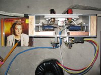
Attached is a picture of my finished amp. The optocouplers are at the end of the blue cable soldered directly to the chip amp pcbs. The cable goes to the lightspeed control unit with the pots and power supply. I really like the idea of being able to put the pots out front in the chassis without increasing the signal path.
Thanks again to all who made this possible!
Gents
You have another convert. After reading this entire thread, I felt that the lightspeed is the best in price performance for high quality attenuation. I wired it into a Peter Daniel chip amp I just completed, and I could not be happier with the performance. Thank you Georgehifi, Panelhead and Mikelm for your thoughtful research. A description of my project with pictures is at:
http://www.diyaudio.com/forums/showthread.php?postid=1272297#post1272297
For those wondering about the matching issue, I really got very lucky. I ordered 8 sorted optocouplers from Allied on a Tuesday and they were at my home in Toronto Canada 3 days later. All were from one batch at "C" range. Out of the 8, I got 3 pairs of very close matches. I did the matching more or less in circuit by putting 6 in a row in an IC receptical in parallel and one other on the other side like a shunt. After applying power and letting them warm up, I measured resistance of all six at lowest level on the pot and took all the readings in a spreadsheet. They would be about 60r. Then cranked the pot up a bit to about 100r and recorded all again. Then I repeated at about 300r.. again at1k and at 2k. With 5 readings on six optocouplers taken in about 30 minutes I had a pretty good read on where the matches were. I pulled out one matching pair and substituted the last 2 of 8 in the rig and measured all at 5 points on the pot again. At this point it seemed obvious where the best two matches were.
Once wired into the circuit the results were very good, and the balance quite stable across the normal listening range. I did wire in a 1000r pot as a balance control per Mikelm's post that I think is a useful addition.
I ran it first on a 9-volt battery behind the 5volt regulator for a couple of hours. I then wired in a 12volt 100ma radio shack power supply in place of the battery. I did not see any degradation in sound.
I did find that my minimum volume is a little high, so I will try pumping up the power a little by playing with the 100r resistors.
Attached is a picture of my finished amp. The optocouplers are at the end of the blue cable soldered directly to the chip amp pcbs. The cable goes to the lightspeed control unit with the pots and power supply. I really like the idea of being able to put the pots out front in the chassis without increasing the signal path.
Thanks again to all who made this possible!
Attachments
wlowes, good work. Glad to see another convert to the Lightspeed flock, also good to hear that maybe the selection process is getting tighter from Silonex, your description of the sound in the other forum couldn't be more accurate.
http://www.diyaudio.com/forums/showthread.php?postid=1272297#post1272297
The way you've stated, it is exactly the way friends I hear it. Once again good work and welcome to the new order.
Cheers George
http://www.diyaudio.com/forums/showthread.php?postid=1272297#post1272297
The way you've stated, it is exactly the way friends I hear it. Once again good work and welcome to the new order.
Cheers George
- Home
- Source & Line
- Analog Line Level
- Lightspeed Attenuator a new passive preamp