Hi George,
Thank you for the reply!!
First on the Amp modules, they are not expensive, and apparently sound very nice.
I know the ociloscope shots seem to good to be true. If the sound is dissapointing I will change them for an other classD make.
We need to cut back on our electricity needs, changing over to classD is a (very) small contribution.
I will mail the manufacturer to ask what to do about the resistor change.
In this situation, what impedance value would you recommend?
Cheers
Peter
peterhenk said:Hi George,
Thank you for the reply!!
First on the Amp modules, they are not expensive, and apparently sound very nice.
I know the ociloscope shots seem to good to be true. If the sound is dissapointing I will change them for an other classD make.
We need to cut back on our electricity needs, changing over to classD is a (very) small contribution.
I will mail the manufacturer to ask what to do about the resistor change.
In this situation, what impedance value would you recommend?
Cheers
Peter
100K if possible.
Common all you guys that haven't voted yet for the Passive Preamp Forum, another 3 votes and we've made it to the top!!!!
http://www.diyaudio.com/request/
Cheers George
ventle said:Hi george(hifi),
<snipped>
Now for something completely else: A company called Clairex manufactures LDRs in packages consisting of two LDRs and a single light source in one package (Clairex CLM3500/2). I realize that the On resistance of these are probably too high to be useful for the lightspeed, but anyways, perhaps something to look into for dealing with matching issues?
Am I missing something or does Clairex no longer make the dual LDRs? This looks like their complete index of products:
http://www.clairex.com/shortform.asp?category=Product_Index&Page=1
Are there still any sources with these parts in stock?
gootee said:
Are there still any sources with these parts in stock?
Tom you will find Vactrol still makes dual element units, but they're not suitable for the Lightspeed Attenuator as I have designed it, but maybe you have another use for it, here is the link go to the bottom for the dual link.
http://optoelectronics.perkinelmer.com/catalog/Category.aspx?CategoryName=Analog+Optoisolators
Cheers George
Nelson Pass said:
I have numerous versions. If I let you have one now, will you
wait patiently for the others?
http://www.palantir.net/2001/tma1/wav/operatio.wav
Copy and paste to address bar
Hals patient understudy.
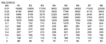
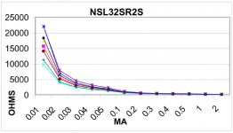
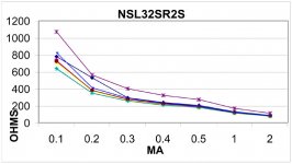
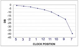
And here's a distortion curve for the NSL32SR2S.
These curves were created with a 600 ohm source impedance,
and the current through the diode was set to produce attenuation
of -0.1 dB, -0.5 dB, -1 dB, -2 dB, -3 dB, -6 dB, and -10 dB
which corresponds to
50 Kohm, 10k, 5k, 2.3k, 1.5k, 600, and 277 ohms.
These curves were created with a 600 ohm source impedance,
and the current through the diode was set to produce attenuation
of -0.1 dB, -0.5 dB, -1 dB, -2 dB, -3 dB, -6 dB, and -10 dB
which corresponds to
50 Kohm, 10k, 5k, 2.3k, 1.5k, 600, and 277 ohms.
Attachments
And last post of the evening, here's a scope shot of the waveform
and distortion, showing the 3rd harmonic content.
This shows that the element's resistance decreases in response
to waveform voltage. Used as a shunt to ground, this is a
compressive characteristic. Used in series, it has an expansive
characteristic.
and distortion, showing the 3rd harmonic content.
This shows that the element's resistance decreases in response
to waveform voltage. Used as a shunt to ground, this is a
compressive characteristic. Used in series, it has an expansive
characteristic.
Attachments
R2 vs R3
I built my first unit from R3S units. It worked fine, even tried it for a while with linear pots to take advantage of the non-linear response. This was entirely because I ordered the wrong parts from Allied.
The next couple were all built using R2. And then swapped to log pots for voltage control. The only difference I could find was more better control at high attenuation.
The R3 grade, and linear pots ramped up quickly. Normal listening was a little hair trigger. Highest attenuation was not enough sometimes with Lowthers. Swapping to more normal efficiency speakers helped with this a bunch.
Sonically, the R2 and R3 sounded identical to me. There appears to be some difference is distortion, but my speakers most likely swap this.
George
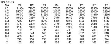
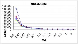
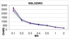
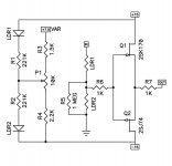
I chose the NSL32SR3 for its better matching, linearity, and range,
and created attached circuit.
The values of R1 and R2 were chosen to make the summation of
the resistors of LDR1 and LDR2 equal to 10K ohm, which then sets
the minimum input impedance of the circuit with the rail voltages
you have (in this case the commonly found +/-15V).
Then you attach the potentiometer with the values shown with the
bottom end going to the -15V rail and the top to a variable regulator.
The nominal value of this regulator is 7.5V, but it needs to be
adjustable so that you get the range you want.
The range that this was adjusted for was -1 dB at the top and
-40 dB at the bottom. More range is possible, but at the expense
of the taper characteristic.
The buffer section consists of matched 2SK170 and 2SJ74, matched
for Idss. If you do not have matched parts and DC offset is an
issue, then consider using an output coupling cap.
The bandwidth of the active buffer is extremely wide, and for that
reason 1K ohm input and output resistors are appropriate.
The distortion of the active buffer is about .003% on a clear day
at 1 V, which is less than you will be experiencing with the LDR
portion of the circuit.
Of course you can tart this up as you like - I consider this the
minimal circuit.
Attachments
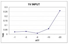
Lastly, here are the distortion figures I got with a constant 1 volt
input to the attenuator. More input voltage naturally results in
greater distortion, except at the -6 dB value, where the 3rd harmonic
distortion of the two LDRs cancels. From -1 to -6 dB, the distortion
is compressive, and from -6 to -40 dB the distortion is expansive.
Any questions?
input to the attenuator. More input voltage naturally results in
greater distortion, except at the -6 dB value, where the 3rd harmonic
distortion of the two LDRs cancels. From -1 to -6 dB, the distortion
is compressive, and from -6 to -40 dB the distortion is expansive.
Any questions?
Attachments
I forgot to mention that because I have not followed the entire
thread, it is possible that I have duplicated something without
knowing it. If that's the case then
Excuuuuuuuse Meeeeee!
😎
thread, it is possible that I have duplicated something without
knowing it. If that's the case then
Excuuuuuuuse Meeeeee!
😎
- Home
- Source & Line
- Analog Line Level
- Lightspeed Attenuator a new passive preamp