Except for the LDR’s the components don’t have to be closely matched. Standard 1% resistors will de the job. And all the voltage references are already very precise.
Patrick:
The capacitors will help to reduce LED noise. After the caps are initially charged they will take no current from the current sources.
Ryssen:
Dale resistors are okay, but not in the same league as Shinkoh / Audio Note Tantalum resistors.
I bought my resistors here:
http://www.partsconnexion.com/catalog/resistors.html
Correct me if I am wrong.
I would use capacitors to maintain a costant voltage, or suppress voltage noise, as capacitors has low impedance at high frequencies, and will shunt any varying components of voltage. I would use inductors to maintain constant current, or suppress current noise, because they resist changes in current.
So if I wish to drive my LEDs with constant current, then I would perhaps put an inductor in series with the LED, rather than a cap in parallel ???
Unless of course one wish to drive the LEDs with constant voltage afterall. In that case, the current source in combination with the cap in parallel with the LED merely acts as a very good low pass filter to surpress power supply noise, not too different from a standard LC filter. But that is not really the same as driving the LEDs in pure current mode.
Patrick
Patrick,
I see what you are driving at but I think that the caps are a good idea on either version of the LDR volume control.
Even with a very good CCS it will be difficult to stop the LED's generating some noise which will be expressed as tiny fluctuations in the voltage across them.
So even if the CCS maintains perfectly constant current, the tiny voltage fluctuations across the LEDs will cause tiny power fluctuations, which will probably cause light emission fluctuations and noise in the resistor element of the LDRs.
Peter,
Thanks for your reply.
Could you please explain exactly what you compare it with when you say this CCS powered circuit sound much better.
Was in a bought lightspeed or a built one ?
Exactly what circuit ?
Did it have caps across the LEDs
Did it have a filtered low noise power supply ?
Until we know all these things it is hard ( without hearing it ) to really understand the significance of the improvement you heard because compared with the original I could say exactly the same about my heavily filtered voltage driven version.
I am not saying that CCS is not better but I would appreciate some more understanding of what you have compared.
( It would be a pity to spend hours building a new cct only to find we had achieved similar subjective results via different methods )
thanks
mike
I would like to try capacitors across the LED's of my Lightspeed clone (based on George's original), can somebody recommend what type/make will be most suitable.
Thanks
Pete
Thanks
Pete
Voltage vs Current Control
I think the better sound heard from the current control is stemming from a better supply. A better voltage supply will provide the same effect.
Mine has simple tracking regs, and is choke loaded. Chokes are on both sides of the LDR to keep ground plane noise out. And a 10 ufd high quality electrolytic across the LDR as close as possible. Maybe 1 cm total lead length. The chokes make up for the high frequency performance of the three pin regs.
Using the chokes did improve the sonics. Using two was much smaller. The cap across the LDR made it better. The sound was excellent to begin with. Better than any of the pots, or switched attenuators I had tried.
Controlling the current sources looks to be much tougher than sourcing some usable chokes. Mine are 1 mH, 250 MA, 1 OHM surplus. Think they were 1.50 USD each. So three dollars. The caps were 7.5 cents, another 30 cents to the total.
I saw pics of Rainwater's unit, he has some monster foil chokes in it. Now that is overkill. Those chokes cost more than my complete unit.
One area with the LDR that is sometimes missed is matching to get the same impedance. Even with the matched LDR's, measing resistance for the control can vary by 10% or so. I use sloppy matched dual pots. Parallel the tracks to help with taper, and mix and match. By using mismatched pots, the measured impedances can track very closely.
Listening has shown that this impredance matching is less critical than expected. I have used some pots in the past that sounded and appeared to track very well. Measurements showed large variations in taper and overall balance. The ear is very forgiving.
George
Pete,
I used 100uF oscons but I think any reasonable electrolytic will have a big effect.
I do not know if esoteric will sound better but I suspect you will get 90% or more of the effect with any type electrolytic.
make sure you get polarity right
mike
I used 100uF oscons but I think any reasonable electrolytic will have a big effect.
I do not know if esoteric will sound better but I suspect you will get 90% or more of the effect with any type electrolytic.
make sure you get polarity right
mike
George/Mike,
Thanks for your replies, I think Ive got some 100mf Panasonic FC's, so will give these a try to start with.
I will also have a look at upgrading the 5V power supply as I am currently using a fixed regulator (cant remember which one) without any other components.
Ive been using the Lightspeed for about 6 months and have been really impressed. It will be interesting to see if it really can sound any better.
Cheers
Pete
Hi Psymo,
try to get used to the correct multipliers and units before you confuse yourself and us.
In this case it's easy to see you meant 100uF.
f=femto F=Farad
u=micro, m=milli, M=mega
k=kilo, K=Kelvin
try to get used to the correct multipliers and units before you confuse yourself and us.
In this case it's easy to see you meant 100uF.
f=femto F=Farad
u=micro, m=milli, M=mega
k=kilo, K=Kelvin
Peter, George, I was referring to the CCS components when asking about matching. I see that has now been answered.
Is it a decent guess that a certain well respected Swiss preamp uses the LDR's with a CCS, and buffer?
Is it a decent guess that a certain well respected Swiss preamp uses the LDR's with a CCS, and buffer?
Mike:
I have compared a built (not bought) original lightspeed and a CCS version using the same optocouplers with 100uF Elna RSH and 47nF foil capacitors direct across the leads of the LED’s. I had placed a 9 pole D-connector between the LED’s and the circuitry to be able to plug it from one circuit (lightspeed) to the other (CCS). The power supply of original lightspeed was threefold stabilized. First a stabilized by a lab power supply and then a double LM317 regulator, the first at 12.6V and the second at 5V. See the attached picture to get an impression.
The CCS version sounded a lot cleaner (like looking through a pair of spectacles that were cleaned), with a more precise soundstage, more spatial and especially with fixed series resistors very, very natural and with an amazing pinpointed imaging. When I am doing listening tests a do a lot of zapping and mainly listen to short tracks. But when I was listening to the CCS version I noticed that I forgot to zap and was just listening and enjoying music. Music was more lifelike than ever before. I have a high resolution audio system with Apogee Duetta planar speakers, so every little detail can easily be observed. I asked my wife to listen to the differences, and although she is not quite a fan of my hobby and hates those ugly big speakers, she heard the improvement right away.
In the experimental setup I used a TL431 as a reference and in the version which is built-in now in my pre-amp I used an LM336-2.5 as a reference with a darlington transistor (BC517) to get the range I need. The end result is even sounding better than the experimental setup. Probably due to the much shorter wiring and the lack of a connector between LED’s.
Patrick:
If you want to suppress LED noise, than you must tackle the source of this noise which is the LED itself. So I see no other possibility than a parallel capacitor.
Peter
Attachments
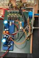
Just out of interest Peter, is that a tube source driving the Lightspeed in the background with multiple stack polypropylene coupling caps?
Cheers George
Cheers George
George:
The capacitors are on the output of the tube stage. The LDR’s are on the input.
Peter
The capacitors are on the output of the tube stage. The LDR’s are on the input.
Peter
details of CCS
Peter,
Any chance you could share the details of your CCS? If it really improves the performance of the unit, I want a CCS in both of mine.
Your voltage driven model you tried is very close to what I am using, except for the chokes. And the low value chokes are really just doing some high frequency filtering, not suppling a steady current.
George
Peter,
> If you want to suppress LED noise, than you must tackle the source of this noise which is the LED itself. So I see no other possibility than a parallel capacitor.
I have no objections to the cap, and I like your circuit a lot. In fact I tried to draw one and could not do it much better.
BUT as I said before, your current cource in combination with the cap is nothing but a low pass filter. Please have a look at the blowtorch thread and you will see examples of that (e.g. shunt regulators driven by a current source).
So as your circuit stands, the LEDs see stabilised voltage, and not stabilised current. But I guess it is an academic discussion. As long as it works ......
I have actually talked to a friend who did his Ph.D. in LED semiconductor Physics. He also recommended driving with stabilised voltage. I shall not bore you with details of our half-hour conversation on hole-electron recombination mechanisms.
Patrick
Panelhead:
See post #1001 for details.
Partick:
Before the CCS design I had drawn a stabilized voltage source version which I never built. I will scan the schematic tomorrow and post it. I didn’t build it because LED’s are rather temperature dependant, so the current they draw will vary with temperature and thus LDR resistance will vary also. But who knows is the voltage source version the winner.
Peter
pietjers said:George:
The capacitors are on the output of the tube stage. The LDR’s are on the input.
Peter
?? so you have a tube buffer after the Lightspeed? and the pots? between the tubes, are they your old level controls before the tubes, before the Lightspeed came along?
Cheers George
George:
What you see between the tubes a 100k DACT stepped attenuator which was my volume control before Lightspeed came along. I used the DACT in shunt mode. You Lightspeed design easily beats that configuration. Now I use the DACT to control the current source. The line amp is mu-follower with a 5687 tube.
Peter
Judging by the amount of coupling caps 10-20uF? in each stack, for your coupling of the tubes to the power amp, your poweramp has a lowish input impedance? what brand or self built is it.
Cheers George
Cheers George
- Home
- Source & Line
- Analog Line Level
- Lightspeed Attenuator a new passive preamp