Oh, I see the original Nelson Pass circuit is still referenced as recently as post 5752!
Nice to see it has stood the test of time (as one would expect from NP!)
Peter
Nice to see it has stood the test of time (as one would expect from NP!)
Peter
Yes I believe it may have been the starter some 13 years ago to the B1 buffer he marketed later. Still at 1kohm quite high output impedance, never tried to lower that series resistor to say 100ohms, to see if things stay stable, maybe if @Nelson Pass watching he can say
Cheers George
Cheers George
Attachments
Last edited:
The Lightspeed Attenuator is an elegant, musical piece of gear. My diy version has been controlling loudness for 11 years. 7.1, three front channels biamped high and low, so a total of 11 attenuators on one volume knob. I would like some kind of volume control between left and right, maybe 2 and 4 dB left, nothing, 2 and 4dB right.
Peterm100: Peter, could you diagram here what you did for balance? Anyone else?
Thanks,
Paul
Peterm100: Peter, could you diagram here what you did for balance? Anyone else?
Thanks,
Paul
Parallel Approach
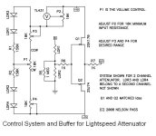
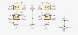
This is a schematic from the pcb production, should get the idea across. Happy to share the gerber files if anyone is interested... RV1 is the balance control, RV3 is volume.
This is a schematic from the pcb production, should get the idea across. Happy to share the gerber files if anyone is interested... RV1 is the balance control, RV3 is volume.
Attachments
Last edited:
Parallel Approach
I just noticed that the 25k label on RV3 is mislabeled on the schematic I posted. It should be 10k, the same as in Nelson Pass’ original design.
I just noticed that the 25k label on RV3 is mislabeled on the schematic I posted. It should be 10k, the same as in Nelson Pass’ original design.
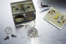
Diameter of each plate is 22mm.
If you can get a hp 3420b cheap somewhere...
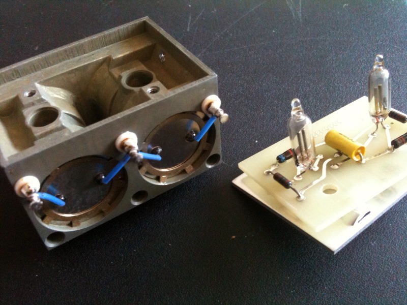
This thing came back to the surface...
A pair of LDRs on each side, but on one side there is a mesh in front of the LDRs, dimming the light, also the plastic is scratched. So it needs polish and remount without the mesh.
Close to the bulb of a working light it goes down to 90 ohms.
Are the LDRs usable for a lightspeed ?
Attachments
Wow that reminds me of my very first prototype back in the 70's, where I had a brass tube with and ldr in each end and the same neon light was in a hole in the middle of the tube.
Cheers George
Cheers George
To all the "Lightspeeders" here at diyAudio and any new ones
OK, time to let all here know that Lightspeed Attenuator has been acquired by a most avid audiophile, and who will do it proud.
His name is Scott Campbell who also resides in Australia in the Sydney country side town of Green Point.
He’s been very committed hi-end audiophile for as long as I can remember. As for his component history I’ll let him tell you.
It was time to let it go after all these years, because it was starting to feel too much like “ground hog day” to me producing them.
He also won’t be doing any orders for the time being, because of the Covid outbreak here, and he will also need to setup his production premises.
His present email is Audio@tradeontheweb.net but no doubt will have another soon, more akin to Lightspeed Attenuator name in the future.
I will still be around for tech assistance, till he finds his feet.
Cheers, and a very big thanks for all your support George
Thanks George & thanks for the kind words.
I’m a passionate audio guy of 60. I’m very proud to have this opportunity with a product I’ve used personally for over 10 years.
George has kindly agreed to remain on in a support role & I'm fortunate to have his knowledge to call upon when needed.
I have some future plans for the Lightspeed, but for now the focus is on supporting existing owners & getting production up & running, once Covid allows.
Cheers
Scott
Hi all,
I a have been a long member of Diyaudio but new to LDR volume attenuators. I mainly restore vintage audio and sometimes use knowledge from Diyaudio to upgrade equipment or find alternative solutions to circuits in vintage equipment. Momentarily I am looking into several volume attenuation options to replace/upgrade existing pots (most carbon). I have read into stepped attenuators and build a few. Used conductive plastic & carbon pots and read into relay attenuators. now I get more and more interested into LDR attenuators, especially developing a compact solution to replace pots in some equipment.
I yet have to read the complete thread but I have a few questions for the experts here:
- Do I need at least 2x2 matched ldr’s
- is it’s easy to do the matching yourself or can matched pairs be ordered somewhere?
- is the LDR comparable to a ladder attenuator or more to a shunt?
- when I would have a 50k pot in an Amp can I use an LDR to replace this with the same resistance
Hi Hirolda,Hi all,
I a have been a long member of Diyaudio but new to LDR volume attenuators. I mainly restore vintage audio and sometimes use knowledge from Diyaudio to upgrade equipment or find alternative solutions to circuits in vintage equipment. Momentarily I am looking into several volume attenuation options to replace/upgrade existing pots (most carbon). I have read into stepped attenuators and build a few. Used conductive plastic & carbon pots and read into relay attenuators. now I get more and more interested into LDR attenuators, especially developing a compact solution to replace pots in some equipment.
I yet have to read the complete thread but I have a few questions for the experts here:
regards
- Do I need at least 2x2 matched ldr’s
- is it’s easy to do the matching yourself or can matched pairs be ordered somewhere?
- is the LDR comparable to a ladder attenuator or more to a shunt?
- when I would have a 50k pot in an Amp can I use an LDR to replace this with the same resistance
If you check the starting page of this thread, most of your questions are answered there.
The LDR matching is done at three places between 1mA to 20mA. (Usually 2.5mA, 10mA and 20mA)
If you’re at all uncertain on construction, I’d suggest you purchase an assembled Lightspeed & proceed from there.
Hope this helps.
Cheers
Scott
Thx Scott.
This helps for sure. After my post I read the first 14 pages and last 10 or so but my summary is that nothing is rocket science and I will just need to build a proto. I am really looking froward to the results.
So my summary thusfar is
regards
This helps for sure. After my post I read the first 14 pages and last 10 or so but my summary is that nothing is rocket science and I will just need to build a proto. I am really looking froward to the results.
So my summary thusfar is
- The LDR attenuator is a shunt design.
- I still have to go for the Solinec nsl 32sr2 as this is the LDR with the lowest start resistance, prefferably the sr2s. I found that Digikey stocks both versions.
- I will do the matching myself and I am thinking of 2 options:
- I will use lab psu to bring the voltage up to 5V and measure the current. Next to that I can measure resistance so i can creat some R vs I graphs for the LDR's
- Or maybe I will just use the lab psu with a 100K pot (just as in the design) and perform the same measurement. My Lab PSU is accurate enough to measure low mA values.
- The quality of the 100k pot does not influence the results. I am not sure yet wether logaritmic or linear is preffered for the pot
- It only uses a few components so it can be very compact
- , but I have to take care of this depending on the application.
- I would like to test it in a Sansui AU X1 integrated amp that has a seperate winding on one of the transformers for controlling the led's on the input selection. This is a rectified 7V so I will use a LT3045 circuit to bring it to a very stable 5V.
- The LDR will be sensitive to differential temperatures over the LDR's. n the Sansui the original pot is located close to one of the power supply heatsinks that powers a class A mm/mc phono stage so I will need to put the LDR in a position that is not influenced by temperature from that power supply or the phono stage.
- That same amp has the option to switch the buffer amp (Flat Amp) on and of. With that flat amp switched of I have nothing between the volume control and the power amp (beside some volume pots on both amp modules). So I will need to measure input impedance of the power amp and flat amp to see how well they match to the LDR. The poweramp has a jeft input stage. I am not sure of the flat amp.
- The phono stage delivers 1Vrms and can drive the power amp without the flatamp. No problems expected here.
regards
Series/shunt design.The LDR attenuator is a shunt design.
Log dual 100kohm pot, as linear will come on too strong early in rotation.The quality of the 100k pot does not influence the results. I am not sure yet wether logaritmic or linear is preffered for the pot
I used to wax pot all 4 thinking the same early on, then I stopped. As it's built on page 1 you don't need to wax pot them as nothing makes them shift out of being matched. You may have to wax pot them if inside an amp.The LDR will be sensitive to differential temperatures over the LDR's.
Cheers George
Hi George,
thx for the feedback. Just have to find a good quality 100k log pot. And I am talking here about mechanical quality. The volume knob is massive on the amp and it has a long axle.
Would it be an idea to glue to two series together and the two shunt LDR's together with thermal glue to have them thermally coupled?
You can if the amp varies a bit in inside heat with hi bias.Would it be an idea to glue to two series together and the two shunt LDR's together with thermal glue to have them thermally coupled?
Cheers George
Another, maybe stupid question. Has anyone tried to use the curve tracing capacibility of a DCA75 pro to perform measurements for matching.
I am thinking of something that does a current or voltage sweep on the led source and simultanously measures the resistance or voltage drop over the source of the LDR. So to get Actual measure graphs iso point measurements. Just thinking out loud. For measureing voltage drop I can use my 4 channel oscilloscope to measure 4 devices at once.
Another idea is to use a reference LDR and couple a second next to it such the voltage drops over the resistive parts substract. A perfect match would give zero voltage. Wheatstone bridge or something like is sometimes used for transistor matching?
regards
I received my 30 pieces of NSL -32sr2s all grade A from Digikey. I am now constructing a measurement jig with ic sockets to measure 10 at once in series with 2V with my lab psu that can deliver 24V.
I have a rotary switch with 200R, 470R, 1k, 2k, 5.11k & 10k that would give the correct current range with 2V
I have a rotary switch with 200R, 470R, 1k, 2k, 5.11k & 10k that would give the correct current range with 2V
Ok I changed the resistor values. I now have 6 steps with 20V on the lab psu. I have my 10 LDR's positioned in series with the color dot on the negative (cathode) side. That should give me:
1) 40k --> 0.5mA
2) 20k --> 1mA
3) 10k --> 2mA
4) 5.1k --> 3.9mA
5) 3k --> 6.7mA
6) 2k --> 10mA
When I measure the voltage over the 10 led leads of the LDRs I get in total 15.73V and this is at 40k setting. So the voltage drop over the series resistor is 4.27V (this is also what I measure). That would give me I~0.1mA and that is also what I measure when I put the DMM in series with the lab PSU.
I guess this also would imply that the resistance of all LDR's in series would be around 150k.
With setting 1 I measure around 662 Ohms which is way to low I think. Something is not right in my setup because I would expect a much higher resistance value at I~0.1mA.
Last edited:
Ok did another measurement this morning. I have a Keithley DMM between the lab psu and the rotary switch with some dropping resistor. Another DMM measures the resistance on the LDR.
I have to play with the outlet voltage of the PSU and the dropping resistor to get the desired current setting. These are some resuls of a quick measurement on one LDR to get an idea on the values that I can expect (Column 1 is the set current and Column 2 is the measured resistance):
0.016 8300
0.06 1200
0.1 637
0.2 348
0.3 205
0.6 130
1.1 95
1.6 76
3.3 49
6.1 36
I think I am alright here and I see that the LDR already goes below 40Ohms at 6.1mA. Mind you that this was a measurement direct after power up. I now have to let everything settle and start measuring. With this setup I could measure to maximum 6.1mA Is that good enough or should I go towards 15mA or even 20mA?
Last edited:

- Home
- Source & Line
- Analog Line Level
- Lightspeed Attenuator a new passive preamp