Also, sorry I forgot, there are only three LDRs or resistors on each balanced channel, not four.
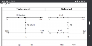
Like on the left channel you'll have a positive and negative line. Each line gets a series resistor and those series resistor terminate into another resistor which is the same resistor. I'm on my phone so I can't draw it. First series resistor A terminates into resistor C. Second series resistor B also terminates into C. Then both A And B lines continue on to the amp.
Few minutes later... Found a pic of what I mean online
Attachments
Last edited:
You have to match up 4 x NSL32SR2 's resistances at 5 different working mA's from 1mA to 20mA for a calibrated single ended stereo Lightspeed to work and be channel balanced at all levels.
With this balanced one, you'll have to match up 8 of them, good luck with that, and then the ambient heat factor will make them go out of calibration exponentially more easily than a single ended one would.
Sure you can keep them calibrated with a real time electrotonic feedback adjustment system, but then that's in the signal path and introduces whatever noise/distortions into the music also, and you've lost the purity of just a passive device.
Cheers George
George you don't need 8 for balanced. 6. He can do it but probably not if he uses the current numbers you always suggest.
Need 4 matches and 2 matched. The 4 and 2 sets should be rather similar but not a big deal. The 4 should be well matched and the 2 should be well matched. But really, 1mA is freaking huge to LDRs. I mean just think about the fact that you use a 100k pot to supply current at, what, 5v?. 1mA is coming in at 5k... So the other 95% doesn't matter? 20mA will ruin any matching you had. It's too much for them to handle and it will forever change the ldr you subject to 20mA. When I used circuits that required matching I tried to keep it under 6mA. You can still get 40R as a minimum resistance at 6mA so why go higher?
Need 4 matches and 2 matched. The 4 and 2 sets should be rather similar but not a big deal. The 4 should be well matched and the 2 should be well matched. But really, 1mA is freaking huge to LDRs. I mean just think about the fact that you use a 100k pot to supply current at, what, 5v?. 1mA is coming in at 5k... So the other 95% doesn't matter? 20mA will ruin any matching you had. It's too much for them to handle and it will forever change the ldr you subject to 20mA. When I used circuits that required matching I tried to keep it under 6mA. You can still get 40R as a minimum resistance at 6mA so why go higher?
the current numbers you always suggest.
The current numbers "I always suggest", give you a channel balanced Lightspeed Attenuator with no need to use forced matching by active feedback means, and even with using 6 NSL's for balanced, your still in a land of hurt, to keep it calibrated with ambient temp fluctuations unless you use forced matching by active feedback means
Last edited:
I've never used forced feedback or any other similar auto adjust. He just needs 4 to match and then two to match. That's no harder than building a lightspeed. Luckily when they match they react to room temperature fluctuations in a similar manner and so the drifting is usually unnoticeable. Its an easy build. It's technically easy to match but a bit of a job. But so what? The result is worth the work. It's maybe expensive to buy enough LDRs but once you've got a few quads a diyer can sell the extra matches recoup the money, and help the next guy.
And your current numbers are still rubbish. 1mA is going to result in just a few hundred ohms in the ldr. When you only match between minimum ohms and maybe two hundred ohms how can LDRs be considered matched when we use them up to 20k? Tell me that.
And your current numbers are still rubbish. 1mA is going to result in just a few hundred ohms in the ldr. When you only match between minimum ohms and maybe two hundred ohms how can LDRs be considered matched when we use them up to 20k? Tell me that.
Thank you! The schematic in #5742 is my missing link. I can calculate the voltage dividers with constant equivalent resistance. The following scenario should lead to the goal - although it is quite labor intensive:
Instead of potentiometer (100K) and the individual normal resistors stored in the circuit, set the target resistance in the signal path 6 times for each volume level and measure the electrical values for it, which are then electrically adjusted and tested in the control path. The best possible heat dissipation must be ensured. The whole thing then works like a stepped attenuator. In my case software controlled.
I should still have a lot of matched LDRs that udailey had sent me very many years ago 🙂
What do you think about this idea?
6 Resistors:
https://www.gearslutz.com/board/att...ed-volume-control-pad-balanced-20db-rev1-.jpg
8 Resistors:
https://www.gearslutz.com/board/att...ed-volume-control-pad-balanced-20db-rev2-.jpg
udaileys schematic:
Uneeda Audio - Build your own attenuator pads
Last edited:
TJF, You can also take a look at the simple circuit that Nelson Pass made.
Mind you, I think the circumstance he is particular to, so sort of a requirement, or one might say, relaxing a requirement, is that only the upper 10-12 dB need be lineair. So he does one test at that range.
Explain: Within a chain with minimal amount of amplification (his power amps typically do 5*, preamps typically 1*) you need only a small part of the attenuation. Idiots like me use a preamp after a potmeter that attenuates 40 or 30 dB's . . in my case, possibly ruining everything called HiFi, because you mght loose something even with the Black Beauty I have on one preamp. Because GeorgeHiFi uses a dynamic shunt so to say, he improves a lot on a standard shunt I think.
The bonus: he uses two LDR's. For balanced, this is easy to convert to four.
Last edited:
The pass circuit is not suitable for me. I need a very precise matching of the impedances and above all a constant equivalent resistance.
Ah, that is a very good argument. {I have a set of constant ohm studio atts - I can understand why}
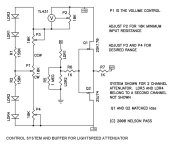
If anyone's interested, this was a buffered Lightspeed Attenuator for driving his low input impedance power amps of the time that Nelson Pass kindly donated, it was later to be called his B1 buffer.
Attachments
Last edited:
TJF don't use your eight LDRs way. You'll have a higher lowest volume. Use the three. We don't need ground the same way as we do in single ended. Just connect ground to the chassis. We are amplifying the difference between the two lines so ground is no longer what we are comparing to.
George my name is Uriah. I am not Chris Daly.
George my name is Uriah. I am not Chris Daly.
If I understand you correctly, you mean 2 x 3 LDRs. That is good. I had confirmed above also so, after I had seen your diagram. I only have to regulate these 6 LDRs - adjusted for each volume level - individually.
So you'll adjust 4 at once with one pot. This will require superb matching. Hope I did well. This is all the series LDRs at once with one device. At the same time you will adjust the pair that connect both lines of a channel together. Do this with one pot or one device.
So that you are not stressing a pot you might use LM334 current source to supply current. Adjust lm334 with one pot. A 5k should do it. Put a small resistor right after lm334. You'll be using like 9v or so, so that resistor will be around 1k. This allows a max of 9ma, just in case. Each ldr needs a 10uf cap and a .1uf film cap on the led side. It helps, trust me. You can use just a lm317 for voltage regulation to power the whole circuit. I just use a small transformer, rectify ac into DC, use a gob of caps to smooth DC and then regulate into the main circuit. I don't like the idea of switching power supplies but that's just me. They do work.
You will not achieve totally stable total resistance. If you're expecting to make the equivalent of a 10k pot, let's say, and expect it to equal 10k at all volume settings this is not going to happen. Also, LDRs should not go below 40Ohms. This means minimum volume will not be dead quiet. It will be actually a listenable level. So.... The ability to make those series LDRs go quite higher than normal at minimum volume will help counteract this. You may consider a mute switch which will short the two lines to each other. See? Fun! You can build your basic circuit and then make all sorts of adaptations later. Don't try to figure it all out at once. Get it working at a basic level first.
Also, if this original 4 don't perfectly move together you can finagle this a little. Like if one always goes high resistance before the rest you can slow this with a parallel high value resistor. If one wont go high enough when the rest do you can finagle this too. Just stick a really high value trimmer pot on the led positive leg to ground and adjust until it works right. These two fixes should not change how it acts the rest of the time because the change we implement this way only mathematically starts to matter when we need it to.
Oh, also, the lower your total resistance (pot value you are trying to emulate) the better. The lower the highest resistance you force the LDRs to achieve the more likely everything matches. It's rare to get LDRs to match at 200R and also 20k. More realistic to expect them to match at 60R and 6k. Plus, lower the value the lower the drifting. Lower the value the more transparent the music. Although, if you prefer that super smooth, tubey sound that is a bit less transparent then 20k is a good goal.
Oh, also, the lower your total resistance (pot value you are trying to emulate) the better. The lower the highest resistance you force the LDRs to achieve the more likely everything matches. It's rare to get LDRs to match at 200R and also 20k. More realistic to expect them to match at 60R and 6k. Plus, lower the value the lower the drifting. Lower the value the more transparent the music. Although, if you prefer that super smooth, tubey sound that is a bit less transparent then 20k is a good goal.
Last edited:
So you'll adjust 4 at once with one pot. This will require superb matching. Hope I did well. This is all the series LDRs at once with one device. At the same time you will adjust the pair that connect both lines of a channel together. Do this with one pot or one device.
So that you are not stressing a pot you might use LM334 current source to supply current. Adjust lm334 with one pot. A 5k should do it. Put a small resistor right after lm334. You'll be using like 9v or so, so that resistor will be around 1k. This allows a max of 9ma, just in case. Each ldr needs a 10uf cap and a .1uf film cap on the led side. It helps, trust me. You can use just a lm317 for voltage regulation to power the whole circuit. I just use a small transformer, rectify ac into DC, use a gob of caps to smooth DC and then regulate into the main circuit. I don't like the idea of switching power supplies but that's just me. They do work.
You will not achieve totally stable total resistance. If you're expecting to make the equivalent of a 10k pot, let's say, and expect it to equal 10k at all volume settings this is not going to happen. Also, LDRs should not go below 40Ohms. This means minimum volume will not be dead quiet. It will be actually a listenable level. So.... The ability to make those series LDRs go quite higher than normal at minimum volume will help counteract this. You may consider a mute switch which will short the two lines to each other. See? Fun! You can build your basic circuit and then make all sorts of adaptations later. Don't try to figure it all out at once. Get it working at a basic level first.
Thank you! Do you have a little schematic by chance?
So you'll adjust 4 at once with one pot. This will require superb matching. Hope I did well. This is all the series LDRs at once with one device. At the same time you will adjust the pair that connect both lines of a channel together. Do this with one pot or one device.
So that you are not stressing a pot you might use LM334 current source to supply current. Adjust lm334 with one pot. A 5k should do it. Put a small resistor right after lm334. You'll be using like 9v or so, so that resistor will be around 1k. This allows a max of 9ma, just in case. Each ldr needs a 10uf cap and a .1uf film cap on the led side. It helps, trust me. You can use just a lm317 for voltage regulation to power the whole circuit. I just use a small transformer, rectify ac into DC, use a gob of caps to smooth DC and then regulate into the main circuit. I don't like the idea of switching power supplies but that's just me. They do work.
You will not achieve totally stable total resistance. If you're expecting to make the equivalent of a 10k pot, let's say, and expect it to equal 10k at all volume settings this is not going to happen. Also, LDRs should not go below 40Ohms. This means minimum volume will not be dead quiet. It will be actually a listenable level. So.... The ability to make those series LDRs go quite higher than normal at minimum volume will help counteract this. You may consider a mute switch which will short the two lines to each other. See? Fun! You can build your basic circuit and then make all sorts of adaptations later. Don't try to figure it all out at once. Get it working at a basic level first.
That is well thought out! Just so I don't misunderstand: You put 10µF + a little foil in parallel to every LED side?
...You'll be using like 9v or so ...
Why 9V? At least the most practical version for me would be 5V (DC side). What do you think? Looking at the spec of the LDR ...
Last edited:
Uriah here
Yeah use the electrolytic and the film. It's no big deal but it does help a little bit. You could get away with a ceramic. We're not trying to tame the cosmos here.
Yeah use the electrolytic and the film. It's no big deal but it does help a little bit. You could get away with a ceramic. We're not trying to tame the cosmos here.
Parallel Approach
I’m late to the LDR game, and still working my way through this thread... Let me just say that adding an LDR-based attenuator to my system was transformational. It does everything described in this thread, tighter bass, crisper highs and a musical presence that my system never had before.
I have built a WS circuit based on the one posted by Nelson Pass long ago. I’m not sure if this is new, but rather then run the LDRs in series as in the original circuit, I arranged the channels parallel to each other and added a pot between the shunt and series LDRs on one channel for balance control.
If this is of interest to anyone, let me know and I’ll share the PCB Gerber file.
Cheers,
Peter
- Home
- Source & Line
- Analog Line Level
- Lightspeed Attenuator a new passive preamp