OK, 5720 posts so a bit hard to find what I am looking for.
But, I think I see from Nelson's graphs, at zero attenuation, the distortion is very low.
So, it is reasonably suitable for a power on mute being in-line with the signal.
I am being defeated de-thumping my system when controlled by the PC USB. Relays don't drop fast enough. Power up I can do. Normal power off I can do. It is on a power fault I am being stumped.
There are no dc thumps from the Lightspeed itself, turning on or off to pass onto the poweramp/s.
But yes it can pass through a "very small amount" of dc offset (at zero volume) from the source to the poweramp/s if they are turned on and off and have dc offset thumps. As the Lightspeed can never go to absolute zero volume.
Cheers George
But yes it can pass through a "very small amount" of dc offset (at zero volume) from the source to the poweramp/s if they are turned on and off and have dc offset thumps. As the Lightspeed can never go to absolute zero volume.
Cheers George
Maybe enough.
Here is my catch-22:
I want things to work simply. One button on/off. No fiddling. Needs to pass the WAF. So I run a USB cable from the pc as a 5V control line to a switched outlet. Turn on the PC and you have turned on the stereo.
PC feeding a Schiit Asgard DAC/pre feeding an XKitx crossover into my Parasound and O-audio amps. Parasound is quite quick to turn on and very slow to turn off. Sub plate has no delays at all.
The XKitz, being single supply and pseudo ground, sends a KaWhump bad enough to blow the speakers. The Schiit sends a small tick, and the PC when it locks to the dac, another tick. I can put on a power sequencer and under normal operation, delays long enough to mask the issues both on power up and down, but on power fault, which happens here not too infrequently, all off at once passes the thump.
So I built a delay relay that shorts the outputs of the crossovers (after the blocking cap, through a 100 Ohm resister, to ground.) Unfortunately, on power off it is so slow the thump passes before the relay drops. I thought about enough cap to keep the crossovers alive long enough for the relay to drop, but my calculations make it look like several coke cans. I have not investigated a supper cap or battery.
My thought is an LED should extinguish a bit quicker and maybe the coupler off resistance is high enough to allow only a subtle sound. Of course it's signal has to drop fast, so a dedicated supply with a lot of bleed.
Additionally, I am considering chopping up the crossover boards and building a +/- soft turn on external power which would eliminate the pseudo ground issue and greatly reduce the DC bias on the coupling caps. I still want a fail safe, fast enough mute and the 32SR2 looks like the safest and lowest distortion bet. J-Fet muting is audible to me.
I did not think I was taking on a project. Just wanted the last set of new equipment I'll ever need. By the time this stuff gets old, I'll be heading for assisted living and my Sony table radio will do just fine.
Trouble is no matter what system, the last thing to be switched "on" should be the poweramp/s and the first to be switched "off"
Cheers George
Cheers George
Last edited:
Yes. And a simple sequencer can do that except for the catch-22. Mains power fault.
My relay takes about 3ms to drop. That turns out to more than enough time for the audio regulators to drop enough to generate the pulse. So a 2-prong attack. It looks like I need to modify the crossovers with a split supply to reduce the problem as much as possible, then add a mute using the opto-coupler as I hope I can get an LED to turn off faster than the relay.
I already have an ultra low noise regulator on it's way from China, but with the mail, who knows when, I still got election propaganda yesterday. That's 12 days late for the international viewers!
Hi DIY fam.
I just heard about LDR today. interesting. I'm trying to power up my new speakers properly (they're built, but not wood finished yet). I'm seeing a couple great amps I can buy reasonably, plenty of power etc. One is a MOSFET (hafler).
Only prob is finding a decent simple preamp! I don't want a big rackmount unit - this has to go in the living room! (WAF!)
I'm sure I'll have to hide the power amp under the fishtank unit anyway.
I see dozens of cheap things from China with a tube sticking out the top...nah.
I also would love to hook up the turntable, but if needed I could buy a phono pre box down the road.
Any suggestions? I'm hoping to spend less than 500 total (can get amp for 200-250).
Is anyone building and selling one of these LDRs on ebay etc? If it can't go to 0, how low can it go?
thanks!
The LDR is an interesting bit of kit. I have some ideas on how to use the couplers for muting. But you really need to have everything tippy top or you could do as well with a $16 Alps pot. It does not do much good if your volume control is .0001% but your preamp is .1%. No disrespect to Lightspeed as it is really nifty, but think "
system" You are looking as shoe string used money. Don't dream about the best of the best. I ran a passive ALPS pot with a selector switch for years as all my stuff was centrally located and I did not have any drive problem needing buffers.
My new simple preamp is the Shiit Asgard. I probably should have bought the JSD Atom instead. These are seriously high end units for less than the Chinese junk.
ANY amp over 7 to 10 years old needs re-capping. Main bank at least and any coupling caps that were electrolytic. Kind of why I bought new. So, consider that in any used amp. They are not as cheap as you think.
Consider a decent integrated amp. Quite a few 50 to 100W units are out there.
The bargain new OK amp is the Emotiva. Not the best of the best, but as good as twice the price. I know of more than one professional mixing studios running Emotivas.
You can make a very very good preamp by getting an $8 Chinese special and replacing the op-amps, stick on one of the ultra low noise regulators and a little aluminum box. Good enough to put quite a few $5000 preamps to shame. A super duper headphone amp is about $12 DIY.
While waiting for the new Parasound, I used my old test amp, a Parasound Z3. Actually very nice sounding after I re-caped it. 45W is not a underpowered amp in spite of what the 1000W club claims if you are running a sub and stick in a subsonic filter on the mains. A really good $2 cap can do wonders.
Disclosure, just took my highly modified Hafler 120 out of service for a new Parasound 2125. Not sure it is an upgrade, but I felt it was time. Nak preamp and Muse DAC out for the Shiit and a JSD tone control. Even with all the criticism about the Asgard DAC being not up to par with the Modi-3, it is clearly an upgrade to my old Muse.
Oh the JSD stuff looks nice! even the 249$ pre would work nicely.
I wish I had a little more time... building the speakers has been a huge project, now I just want it done so I can listen to them . I'm sure i"ll take on more DIY in the future, re-capping and replacing op-amps doesn't sound hard at all.
Most important is the shiny WAFFY box 😀
I had trouble finding Emotiva, but it looks like they ship to Canada, so I may just order the basX A-100 as i hear great things about it with speakers, headphones, etc. AND it has a volume knob.
Hello to all.
I have read the first few pages to find what I am trying to understand and I am not sure I have found it.
there are over 500 pages to read, have mercy.
if anyone wants to answer me I would like to know the following:
I understood that the LDRs are not identical and therefore it is necessary to do a search to find those that are closest to equality between them.
I did not understand if this difference concerns the current (mA) -resistance (ohm) curve or if it is the total resistance measured at its ends that is different.
@arivel
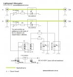
You know each of the 4 x NSL32SR2/S have 4 legs in each package ? 2 are for the LED section and 2 are for the LDR section.
You power up the LED section (2 legs) using the led tester on my first post and measure the LDR section (2 legs) using an ohm meter.
And at 5 different led power from 1mA to 20mA you match the 5 different ohms readings of the LDR section for a total of 4 NSL23SR2/S Then you have a quad matched set.
You "can" match at 3 different powers but you won't get left and right channels tracking as good, and probably hear the imbalance.
Cheers George
so if I understand correctly, the problem is the curve of the resistor , which is not superimposable one on the other.
Last edited:
Yes the ldr resistances are never the same for the same given led illumination intensities, they have to be matched up.
Some Lightspeed clones try to auto force match them with active circuits with extra mA to the weaker ones on the run, not only are they then included into a sort of active feedback network.
But there's a big problem with that some led/ldr could easily be over powered to meet the lower resistance of other led/ldr and will lower life expectancy greatly.
That's why it's best to do them manually as I've outlined, as none get over powered or under powered, as they all receive the same current.
Cheers George
Yes... I did it today...
After many hours of measuring and selecting...
Works perfect, but it seems that I have some crackling and noise... Because of bad contact or long wires that collect all dirty things. Or perhaps something else...?
Now is connected output from Apple Mac mini (youtube) and output is LM3886 amplifier. It's not recommended chain, but works wonderful...
Boris
Attachments
Last edited:
Yes,it sounds heavenly...
Question for George... In minimum potentiometer position I can hear the sound. I tried to read and find where is this problem described, but there is over 5700 posts and I read about 200 pages. Cannot see... Is there any fast solution for this in a few words...? I did it exactly as you explained. No problem, fine works and souns great, but in the lowest position still have the music and it's not silent...
Thanks,
Boris
Question for George... In minimum potentiometer position I can hear the sound. I tried to read and find where is this problem
No problem as they can never go to 0ohms, there's always some very small amount of signal.
Hint: never leave them powered up full up or full down, if not listening for a few days, as this powers up one pair of the leds to full power, and "could " halve their life expectancy
Cheers George
No problem as they can never go to 0ohms, there's always some very small amount of signal.
Hint: never leave them powered up full up or full down, if not listening for a few days, as this powers up one pair of the leds to full power, and "could " halve their life expectancy
Cheers George
Last edited:
Thank you George.
All is clear.
You did great job, so beautiful sound from the beggining, cannot explain or tell what the difference regarding to classic graphite potentiometer, even 24 step switch... Space, deep, analytic, drums are so real...
Respect!
Boris
All is clear.
You did great job, so beautiful sound from the beggining, cannot explain or tell what the difference regarding to classic graphite potentiometer, even 24 step switch... Space, deep, analytic, drums are so real...
Respect!
Boris
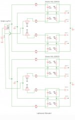
I've been out of the thread for a few years and am currently thinking about building a slightly more complex Lightspeed. In principle a balanced LA. See for example the attached schematic I found here. However, I can't see here how the individual terminating resistors result in connection with the individual voltage divider values (in connection with the 100k potentiometer). Or rather which calculation approach is behind it.
Maybe someone can tell me what accuracy, or what calculation approach to expect with this or any other balanced approach. A voltage divider model with constant terminating resistance over all stages would be ideal.
Maybe someone can tell me what accuracy, or what calculation approach to expect with this or any other balanced approach. A voltage divider model with constant terminating resistance over all stages would be ideal.
Attachments
May be a little programmable DAC could do the job to control voltage of every single of the 8 LDRs and every step of volume...
This won't work. It won't work well anyway. There is no calculation because LDRs are not linear and are not predictable and do not act like their datasheet would suggest. You may consider programming a chip to monitor and adjust or to build a database of current into ldr and the corresponding resistance.
- Home
- Source & Line
- Analog Line Level
- Lightspeed Attenuator a new passive preamp