Your right now that i think about it, each track in the pot is driving both LDR's at the same time.
The difference is small enough that i can live with it, but for anybody else building one stick with the recommendation of buying at least 24 for matching.
The difference is small enough that i can live with it, but for anybody else building one stick with the recommendation of buying at least 24 for matching.
Quads are the original designers recommendation.
But for good stereo balance a pair of duals is very good.
The quads are reputed to give a better turn up, turn down feel/sound, but this is not critical to stereo balance.
It's the matching of the two series devices and the matching of the two shunting devices that matters for balance.
Your set should get you some pairs. select two pairs that are similar.
BTW, the higher resistance at your maximum current can be used for the series devices.
The duals with a lower resistance at your maximum current are more useful in the shunt location.
Thats what i ended up having to do, two matched for the series resistance, and two matched for the ground shunt but with a slight difference between each set.
I may have used the lower resistance pair for the series shunt, will have to double check that. I just went with the pair with the tighter tolerance for that section.
I may have used the lower resistance pair for the series shunt, will have to double check that. I just went with the pair with the tighter tolerance for that section.
Andrew is right, dual mono (attached) will solve your problem, of not matching well. About 20% of my sales now are dual/monos, And for some unexplained reason customers that have both units say the dual mono sounds better, I believe it's because they can get prefect imagining even with unbalanced system/rooms configurations.
Also the quad matching gives a better log feel to the volume control rotation and have better/tighter i/o impedance variations.
Cheers George
Also the quad matching gives a better log feel to the volume control rotation and have better/tighter i/o impedance variations.
Cheers George
Attachments
I wasn't intending two separate vop pot knobs.
I am referring to a normal wiring arrangement with the dual track stereo vol pot.
It's only the matching of the LDRs that I was calling up as two duals, rather than one quad set
I am referring to a normal wiring arrangement with the dual track stereo vol pot.
It's only the matching of the LDRs that I was calling up as two duals, rather than one quad set
Your right now that i think about it, each track in the pot is driving both LDR's at the same time.
The difference is small enough that i can live with it, but for anybody else building one stick with the recommendation of buying at least 24 for matching.
Easier to use a LDR board where Left and Right anode current can be trimmed
and if current is stable that stays that way.
Cheers / Chris
Attachments
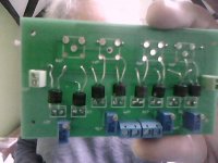
Finally got around to testing this and it seems to work perfectly. I ended up building a simple LM317 supply for it which i may try and improve on now that i know the module is a keeper.
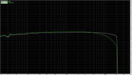
I found the attached pic very interesting, i used RMAA to plot a frequency response with the LDR and a regular carbon pot. I was surprised how much high end gets lots in a cheap pot...
Thanks all for the help!
I found the attached pic very interesting, i used RMAA to plot a frequency response with the LDR and a regular carbon pot. I was surprised how much high end gets lots in a cheap pot...
Thanks all for the help!
Attachments
I have never done a frequency response measurement comparison, between LDR's and potentiometers.
This is very interesting mcander what brand and value pot was this, as -1.6db at 20khz would easily be heard?
Maybe this is why so many say that the highs of LDR's are so much sweeter/transparent and extended than pots, not to mention the bass and mid's sounding superior as well.
I believe it is the actual poor touch contact (diode effect) of the wiper (metal) and resistive track (carbon) of a pot being two dissimilar materials, compared to one material with no touch contact of ldr's is the difference in sound.
Cheers George
Last edited:
The pot i used for testing was an Alpha so it was of somewhat decent quality. Its fairy new but hasn't had that much use as its spent its life on my prototype board testing out different amp circuits. In other words, its not an old dirty worn out unit.
RV24BF-10-15R1-A100K Alpha (Taiwan) | Mouser
RV24BF-10-15R1-A100K Alpha (Taiwan) | Mouser
The pot i used for testing was an Alpha so it was of somewhat decent quality. Its fairy new but hasn't had that much use as its spent its life on my prototype board testing out different amp circuits. In other words, its not an old dirty worn out unit.
RV24BF-10-15R1-A100K Alpha (Taiwan) | Mouser
A 100kohm pot would have a high output impedance, and if your measurement leads that were attached to it's output and had high capacitance, this "could" be the reason for that hf roll off.
The measurement lead would have had to be something in the order of 200pf for a meter for that to happen, if that were the case for the HF roll off.
Try a 10kohm pot to do the same measurement again instead of a 100kohm, as the Lightspeed mimics a 10kohm passive pot in input and output impedances.
Cheers George
Help enough high volume
Hello olds and new friends.
I´m happy to see you stay here.
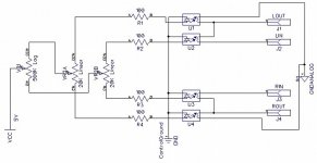
The problem in that with the pot in minimun, the sound is very high. I think, I can put more value for R1 to R4, but I´d like know other opinion.
I suppose the reply any post of this thread but I´ve don´t cant find it.
Thank you very much in advance for your help.
I use this schematics:
Best regards
Jose
Hello olds and new friends.
I´m happy to see you stay here.
The problem in that with the pot in minimun, the sound is very high. I think, I can put more value for R1 to R4, but I´d like know other opinion.
I suppose the reply any post of this thread but I´ve don´t cant find it.
Thank you very much in advance for your help.
I use this schematics:
Best regards
Jose
Attachments
Thank you very much George for your quick reply.
I don´t remember how I puted really, I´ll see tomorrow, but I´d like have the external balance.
Looks a good idea put Vr1 in your schematics with only one 1k trimpot in the louder chanel?
I don´t remember how I puted really, I´ll see tomorrow, but I´d like have the external balance.
Looks a good idea put Vr1 in your schematics with only one 1k trimpot in the louder chanel?
The positive supply for both series LDR's for left and right channel get driven from one point and one segment of the 100kohm pot.
Same goes for the shunts, but from the other segment.
Yours does neither.
Cheers George
Same goes for the shunts, but from the other segment.
Yours does neither.
Cheers George
Dumb question I guess. I have been looking into TVC passive preamps as the optimal solution. But now I find this thread. I have not read it deeply yet. However, the idea presented at the beginning is that the signal path only sees a single soldered resistor and does not see a potentiometer with its rubbing metal to metal connectors.
However it seems to me that any bad effects due to the potentiometer would be passed onto the signal through the opto-resistor chip albeit perhaps buffered away. So is the system truly isolated from the pot? A devil's advocate might say yet another interface in addition to the pot has been made.
However it seems to me that any bad effects due to the potentiometer would be passed onto the signal through the opto-resistor chip albeit perhaps buffered away. So is the system truly isolated from the pot? A devil's advocate might say yet another interface in addition to the pot has been made.
Last edited:
Dumb question I guess. I have been looking into TVC passive preamps as the optimal solution. But now I find this thread. I have not read it deeply yet. However, the idea presented at the beginning is that the signal path only sees a single soldered resistor and does not see a potentiometer with its rubbing metal to metal connectors.
However it seems to me that any bad effects due to the potentiometer would be passed onto the signal through the opto-resistor chip albeit perhaps buffered away. So is the system truly isolated from the pot? A devil's advocate might say yet another interface in addition to the pot has been made.
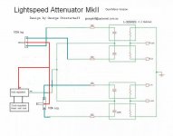
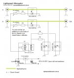
Hi bcc1955, attached is the schematic, the green overlay is the signal path.
The volume control (led controller) has nothing to do with the signal path.
Cheers George
Attachments

The opto chip modulates the resistance which is how it works. But I guess it is fair to say that the connection with the pot and the signal is indirect and perhaps any pot based distortion (as opposed to weed based distortion which intensifies music satisfaction IME) is buffered/muted by the NSL32SR2S opto-coupler and improves the sound we hear. That would appear to be the case for this system?
No modulation. The ldr is a resistor so if you look at the schematics you'll see the ldrs create a voltage divider. Thats how it attenuates. There is no electrical connection between the pot and the resistive side of the ldr. None at all. Its light that increases or decreases resistance which then changes voltage division equation. So the pot could distort all it likes...you'll never hear it as its not in the same electrical circuit.
- Home
- Source & Line
- Analog Line Level
- Lightspeed Attenuator a new passive preamp