no, except if you are very lucky at one or two points in the attenuation range..................Three questions/thoughts about your optical attenuator...
1) Can the channel balance ever be as good as a carefully spec'd switched resistor network?
The Control side is COMPLETELY separate from the Audio side, all that matters is that the control voltage/current does not vary once set.2) It seems the main advantage you claim for the optical device - as compared to switched stepped resistive-ladders (L-topology) attenuators - revolves primarily around the elimination of the switch. Let's just say one accepts this and puts it to one side for the moment, what I don't see mentioned is the actual sonic quality of the resistive element itself. It seems to me that although with a switched resistor network one does incur the liability of switched contacts, one also benefits from having the freedom to spec the quality of the the resistors themselves.
By way of example, lets look at the following: Lets say we attenuate to a comfortable level on your optical device, and then we make a note of the arrived at series and shunt values, and then we solder up the equivalent L-pad using say - the well known Vishay bulk foil resistors. Now, at least for this single attenuation setting, we can connect up in the same way as to the optical device without any switch in the signal path and we can compare apples with apples. Shouldn't the advantage then go to the Vishay L-pad? Further, won't channel matching be easier to nail with Vishays?
no, except if you are very lucky at one or two points in the attenuation range.The Control side is COMPLETELY separate from the Audio side, all that matters is that the control voltage/current does not vary once set.
I know that the control side is completely separate, but the point I was raising was the sonic quality of the optical resistors themselves, compared to a precision foil resistor such as Vishay or Charcroft.
Yes I'm aware the control side is separate.
The point I was focussed on was the sonic quality of the optical resistors themselves compared to a precision foil resistor such as Vishay or Charcroft
The point I was focussed on was the sonic quality of the optical resistors themselves compared to a precision foil resistor such as Vishay or Charcroft
If You'd read all the posts carefully, You would notice, that some people, starting bwith George, claim the material that's in tyhe signal path in LDR sounds better than anything else used for this purpose. And I agree, though I have not compared them to as many things as George has done.
Stop thinking and start doing and listen.
Stop thinking and start doing and listen.
"Stop thinking and start doing and listen" is always good advice. What it usually entails and initiates is 6 months of experimentation and a load of cash thrown at experiments...
"Stop thinking and start doing and listen" is always good advice. What it usually entails and initiates is 6 months of experimentation and a load of cash thrown at experiments...
Just do a breadboard one as I've outlined in the first post.
http://www.diyaudio.com/forums/anal...attenuator-new-passive-preamp.html#post924390
And the max you will spend is around $50-$80 and a day to get it working.
Remember though that some of the NSL's ldrs are not light tight, and any ambient light around them can effect them, you can find the odd one that's not light tight by shinning a powerful torch light on it while matching the resistances up.
Cheers George
I have compared LDRs to many other resistor materials, and it is simply superior.
Also, the balance does not need to be perfect. Wire in a balance POT. When you get up to change the volume, adjust the balance if necessary. I found I seldom ever touched the balance unless the source material was off.
It really only takes a short time to make one of these things. You will not be disappointed.
Thanks George and Wlowes.
I guess I'm just having a hard time with the concept that any variable resistive element could be as sonically good as a fixed precision component like a Vishay/Charcroft resistor part.
What is the actual resistive material in these things?
But anyway as you say, the experiment is easily done. I'll look further into it. Appreciate the help...
Thanks George and Wlowes.
What is the actual resistive material in these things?...
Cadmium Sulphide (Cds) "inorganic" evil stuff, thank god they come in a hermetically sealed package, so don't break it open and sniff it.
Then if your a tube aficionado, you know the best tubes from yesteryear used Nickel (Ni) plates, also evil stuff.
Also the beryllium (Be) tweeters and mids of the old Yammy NS1000's and the newer Focal/JMLabs speakers, also evil stuff.
Then the Ozone (O3) that the best Plasma tweeters put out, and ESL's when they crack, more evil stuff.
Seems in audio anything evil is good, pass the Scotch bottle, so I can round things off nicely will I listen.
Cheers George
Last edited:
Cadmium Sulphide (Cds) "inorganic" evil stuff, thank god they come in a hermetically sealed package, so don't break it open and sniff it.
Then if your a tube aficionado, you know the best tubes from yesteryear used Nickel (Ni) plates, also evil stuff.
Also the beryllium (Be) tweeters and mids of the old Yammy NS1000's and the newer Focal/JMLabs speakers, also evil stuff.
Then the Ozone (O3) that the best Plasma tweeters put out, and ESL's when they crack, more evil stuff.
Seems in audio anything evil is good, pass the Scotch bottle, so I can round things off nicely will I listen.
Cheers George
Yes, I've handled a few beryllium domes in my time...but never sanded them! The Rockwool I use inside speakers is perhaps not evil, but certainly nasty when it gets in one's throat...I don't trust it at all. As you say, best to wash it down with Scotch and forget about it...
Huss
I recall another poster indicating that in his experience the order from best to worst sound was:
- Rhopoint wirewound (I believe with Manganin)
- Home made Manganin wirewound with low inductance wind
- LDR
- all others varying varying levels of degredation
I use Manganin with great success, but only practical for small values up to few hundred ohms. I did compare a variety of boutique resistors up to bulk foil. LDR to my ear was better. To make a switched ladder would cost a fortune with Rhopoint. The lightspeed is just a very good price performance. Very good autoformers from Slagle also excellent. Again lightspeed is the winner on sound / $.
Hi All,
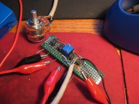
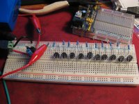
I bought a dozen of these LDR's to experiment with, should really have bought two dozen as i underestimated how much variance they have. I did manged to get four close enough that i can trim them to match and got a board up and running. My question is whats the current consensus in relation to power supplys and bypass caps across each of the diodes?
I've read most of the thread and get the impression 100nf is the norm but i've seen some people went as large as 100uf lytics across them. Would appreciate some insight there. For testing i've just been using a 12v battery supply and 7805, but really looking for advice for the most appropriate power supply to build.
Cheers,
Mark
Attachments
Hi All,
I bought a dozen of these LDR's to experiment with, should really have bought two dozen as i underestimated how much variance they have. I did manged to get four close enough that i can trim them to match and got a board up and running. My question is whats the current consensus in relation to power supplys and bypass caps across each of the diodes?
I've read most of the thread and get the impression 100nf is the norm but i've seen some people went as large as 100uf lytics across them. Would appreciate some insight there. For testing i've just been using a 12v battery supply and 7805, but really looking for advice for the most appropriate power supply to build.
Cheers,
Mark
Hi Mark, this is what I use, and never had any trouble with calibration drift, ever!
Cheers George
Attachments

Thanks George, that looks like a newer rev of the circuit i used to build the board. The calibration seems nice and stable once dialed in, but it does seem to need to run for 20-30mins before everything settles down. This thread just seemed to get lost in elaborate constant current designs which went a bit over my head at times. Is the 7805 good enough, or is there anything to be gained by using more sophisticated lower noise regulators?
Cheers,
Mark.
P.S. Thanks for sharing the design, its threads like this that really make this site
Cheers,
Mark.
P.S. Thanks for sharing the design, its threads like this that really make this site
It's perfect the way it is, we've done many A/B's with group listens, with expensive elaborate power supplies, and you cannot hear the difference, even with battery power some 10% "thought" they could hear something.
The only time a difference was noticed is when we used a smp wall wart, and this then can be measured with slightly more hf noise on the output. But it's hard to see without a good scope, as it's down around 20uV of hf noise.
Cheers George
The only time a difference was noticed is when we used a smp wall wart, and this then can be measured with slightly more hf noise on the output. But it's hard to see without a good scope, as it's down around 20uV of hf noise.
Cheers George
No probs.
Also that the LDR's themselves are so slow in electrical terms to react to "volume control level changes", that in a way they are self damping/filtering of sudden quick momentary minute changes in power supply characteristics.
Cheers George
Also that the LDR's themselves are so slow in electrical terms to react to "volume control level changes", that in a way they are self damping/filtering of sudden quick momentary minute changes in power supply characteristics.
Cheers George
Last edited:
I had noticed that as i was changing the volume level with multimeters connected. I actually like the idea of a soft volume change, makes a nice change from the stepped attenuators i am used to.
I also found the tracking isnt perfect between channels throughout the range, but when you think about it you only ever use 1/3rd of the range of a volume pot anyway so i'll just calibrate the two channels to match in that range. I'm suspecting the imbalance is from the 100k pot.
I also found the tracking isnt perfect between channels throughout the range, but when you think about it you only ever use 1/3rd of the range of a volume pot anyway so i'll just calibrate the two channels to match in that range. I'm suspecting the imbalance is from the 100k pot.
I had noticed that as i was changing the volume level with multimeters connected. I actually like the idea of a soft volume change, makes a nice change from the stepped attenuators i am used to.
I'm suspecting the imbalance is from the 100k pot.
Yes I think it's a nice feel, as you say "soft feel".
And sorry Mark, no the imbalance is not from the 100kohm dual log pot that's impossible, it's because your quad matching of the NSL32SR2S's wasn't tight enough.
Cheers George
- Home
- Source & Line
- Analog Line Level
- Lightspeed Attenuator a new passive preamp