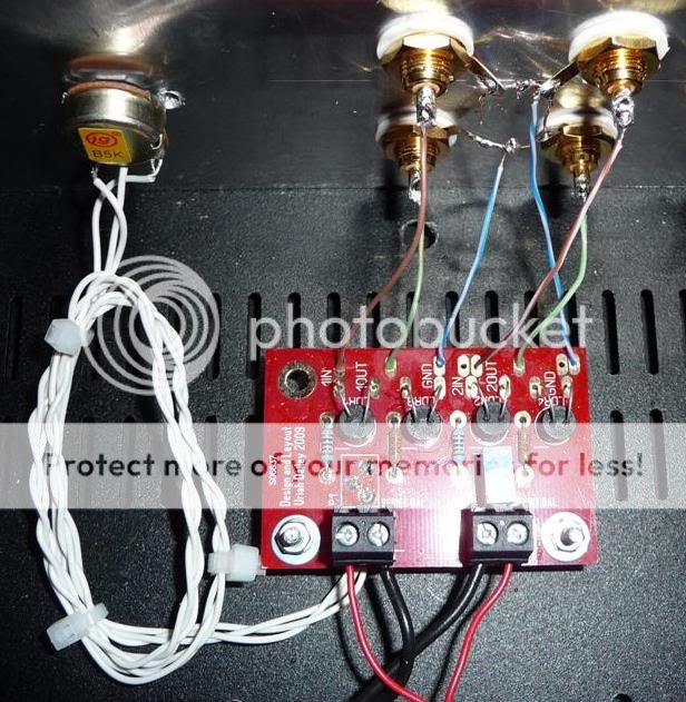
Hi Richard. Can you post a pic or send one to me of your set up? I wonder if you have one of two possible problems
1: Put shunt LDRs in series spot
2: Wired 5k pot in wrong.
Uriah
1: Put shunt LDRs in series spot
2: Wired 5k pot in wrong.
Uriah
I dont think the calibration of shunt has anything to do with it at all. As soon as you turn the volume up a little bit that 200R trimmer stops having any effect on centering the image as it becomes a minor percentage of your position on the 100k pot.
Uriah
Uriah
When I say series in shunt spot basically what I mean is this
We have across the board 4 LDRs. Lets call them ABCD and they are in that order. A is shunt, B is series, C is shunt, D is series. So if we took a pair out of the bag and put them in the board the proper way would be that the pair would either go in A and C or in B and D but NOT AB or CD.
Uriah
We have across the board 4 LDRs. Lets call them ABCD and they are in that order. A is shunt, B is series, C is shunt, D is series. So if we took a pair out of the bag and put them in the board the proper way would be that the pair would either go in A and C or in B and D but NOT AB or CD.
Uriah
Hi Uriah
I didn't take a note of the LDR numbers I inserted in series or shunt. They were inserted in pairs and I believe I soldered the lower resistance pair in to shunt location.
I didn't take a note of the LDR numbers I inserted in series or shunt. They were inserted in pairs and I believe I soldered the lower resistance pair in to shunt location.
An externally hosted image should be here but it was not working when we last tested it.
Richard, Have you seen this?
https://docs.google.com/fileview?id...DUtZTkyOS00YjU2LTk1ZDEtZjZiYjg1OTNjMzdm&hl=en
https://docs.google.com/fileview?id...DUtZTkyOS00YjU2LTk1ZDEtZjZiYjg1OTNjMzdm&hl=en
When I say series in shunt spot basically what I mean is this
We have across the board 4 LDRs. Lets call them ABCD and they are in that order. A is shunt, B is series, C is shunt, D is series. So if we took a pair out of the bag and put them in the board the proper way would be that the pair would either go in A and C or in B and D but NOT AB or CD.
Uriah
Yes I soldered them in the correct location. 1 and 3, 2 and 4
Richard, Have you seen this?
https://docs.google.com/fileview?id...DUtZTkyOS00YjU2LTk1ZDEtZjZiYjg1OTNjMzdm&hl=en
Yep
Okay, from the top it looks fine. Thank you for the pics.
I would look to your balance pot and see if it is wired correctly. The Wiper should be the middle hole in the 'series balance' spot. If you switch the outer wires from the 5k pot around then the balance will work in the opposite direction.
Uriah
I would look to your balance pot and see if it is wired correctly. The Wiper should be the middle hole in the 'series balance' spot. If you switch the outer wires from the 5k pot around then the balance will work in the opposite direction.
Uriah
Okay, from the top it looks fine. Thank you for the pics.
I would look to your balance pot and see if it is wired correctly. The Wiper should be the middle hole in the 'series balance' spot. If you switch the outer wires from the 5k pot around then the balance will work in the opposite direction.
Uriah
Yes the pot is fine
Richard, When I search for "richard's" who have bought from me there is only one so I am assuming its you. You have built a few of these. I trust you have done everything correctly and maybe I am the one who made a mistake. If you send it back to me I will test it and either fix it or send you a new kit.
Uriah
Uriah
Hi Uriah, I just received your board today w/ 4 matched LDR's plus parts. Amazing value with the matching printouts and pre-bent LDR leads. I haven't wired it into the board yet just wanted to thanks for making it available.
Stan
Stan
Stan, Thanks for the thanks. Make sure you bend those leads the right way to get the dot on the side of the LDR to match up with the board before you solder them in. The LDRs are bent to fit in my matching jig. Wish I could claim I prebent them for the board 🙂
Uriah
Uriah
Dears,
I just done a mod in my Lightspeed attenuator and the result is good to me.
I added a decoupling cap for each LED on the board. The caps are Elna Silmic II 10uF.
With this mod, the sound is warmer, smoother, and more forgive. The bass is also extended. The background is darker and cleaner. An easy and nice mod overall. Highly recommended.
Has anyone put together the Nelson Pass version with the buffer? I made one and I've got a slight channel imbalance and I can't get my head around how to level it out. Any ideas would be appreciated.
Buffer? is this the B1 by Nelson Pass?
A buffer passes the signal straight through without inversion and without gain.
The output is very slightly lower than the input and the lower the load resistance/impedance the bigger the voltage loss through the buffer. Expect 99% of the input voltage across a normal output load.
Any imbalance between channels must be due to an error, either elsewhere in in the B1 assembly.
Hi Andrew, thanks for the input. Nelson had Lightspeed version with a jfet buffer to help drive amplifiers with lower input impedance. It has +/- power supply so there is no provision to trim the ldr's with a pot to ground like George's original. He has a schematic somewhere in here I just can't point it out at the moment. I'll have to wade through to find it.
From Nelson for the Lightspeed Attenuator to use with lower input impedance power amps, but still rather high output impedance at 1k.
Whats good is that it's dc coupled.
Cheers George
Whats good is that it's dc coupled.
Cheers George
Attachments

Last edited:
While Nelson has provided a position for a regular pot to be in control of the volume, the LDRs values will still alter the volume. Have you implemented the circuit for the LDRs power just as George has shown us? If so you will have two 1k trimmers in series with two of the LDRs. Turn the system on, play some music, and change one of those trimmers til you get a good balance.
Uriah
Uriah
- Home
- Source & Line
- Analog Line Level
- Lightspeed Attenuator a new passive preamp