
Are those meters in microamps? Or less? If not you wont see them move 🙂 Might put that on your amp if its in mA to A.
Uriah
Uriah
I am testing LDRs with thermistors in series with trimpots today. Put them in series and let the thermistor settle down then dial it in to ~21k then put it outside and see what happens. Its not very hot today unfortunately. Usually we have 100F+ and today it seems maybe we will hit 90F. But I suppose its a decent test anyway. I should hook up a LM334 in temperature reading style, then I can see what the temp is outside and graph out my data. LOL guess I could do that with a thermistor to but I cant understand the math that goes with most of these thermistors. Its a try and see experiment.
Uriah
Uriah
udailey said:Are those meters in microamps? Or less? If not you wont see them move 🙂 Might put that on your amp if its in mA to A.
Uriah
0-15ma
Attachments

Suppose you use 5VDC to supply your LDRs and you turn your 500k pot up 10%. The two LDRs drawing the most current (the shunt at this point) will be using I=V/R or Current = 5VDC/50k so .0001A, or one tenth of one milliamp.
🙂
Uriah
🙂
Uriah
Ehh, maybe waste then
But it was to monitor overloading draw
How will it look then ?
Smal issue puzzles me
George has recommended to turn down volume when not in use, but powered on
To minimise wear on LDR
But then the shunts will draw max, or ...?
Wouldnt the middle position give lowest draw on all LDR ?
Or I have misunderstood it
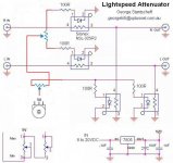
btw, the previous pot connection I showed might have been wrong
I reckon it should look like this ?
But it was to monitor overloading draw
How will it look then ?
Smal issue puzzles me
George has recommended to turn down volume when not in use, but powered on
To minimise wear on LDR
But then the shunts will draw max, or ...?
Wouldnt the middle position give lowest draw on all LDR ?
Or I have misunderstood it
btw, the previous pot connection I showed might have been wrong
I reckon it should look like this ?
Attachments
tinitus said:
George has recommended to turn down volume when not in use, but powered on
To minimise wear on LDR
But then the shunts will draw max, or ...?
Wouldnt the middle position give lowest draw on all LDR ?
Or I have misunderstood it
Always leave the volume in the centre posistion when not in use than way you can leave the Lightspeed on 24/7.
Another thing Tinitus the (wall wart) power suppy you posted in post 2362, just make sure it's a linear and not a switchmode as I have measured a doubling of noise when compared to a linear power supply on the audio outputs of the Lightspeed Attenuator when a switchmode was used.
Mind you it was in the order of 500uV for the linear vs 1mV for the switchmode, but then we are searching for the ultimate.
Cheers George
georgehifi said:
Another thing Tinitus the (wall wart) power suppy you posted in post 2362
just make sure it's a linear and not a switchmode
Cheers George
Hi george, thanks for notice it
But its just an AC-AC
So just an extern trafo
I may just use a very small trafo built in instead
Switchmode is not my kind of thing either
Noisy things
Your info confirms it, thanks
Tinitus,
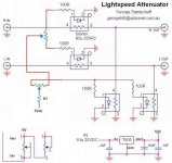
The schematic doesnt make sense. Also, we dont know what pot you are planning on using.
Uriah
The schematic doesnt make sense. Also, we dont know what pot you are planning on using.
Uriah
Power supply
If I have understood correctly the LDR will try to draw all they can, until they blow
So, the resistors have to "eat" all of the not wanted power
In short this means that power supply will run at 100%
The regulator should probably not be the limit of that
That leaves us with the trafo as limiting factor
I suppose all this means that the trafo will be loaded 100% all the time
I have found small EI trafos with 1x 6V/0.3A
Or print board trafos with 1x 6V/0.12A
Or tyhe extern one with 9Vac/0.5A
I suppose 6Vac should be enough for a 5Vdc reg
But which to choose
udailey said:Tinitus,
The schematic doesnt make sense.
Also, we dont know what pot you are planning on using.
Uriah
Ehh, what doesnt make sense
I suppose SPL will rise when impedance is lowered to main LDR in series ?
Pot is the 500K from you
Balance pot is different
Attachments
The resistors are in series so the dont "eat" the power they simply restrict the amount of current allowed to flow through. If a resistor goes from hot to ground THEN it "eats" the power. Dont worry about your supply size. Anything you have around will do. Remember the example of power that is being used? The entire circuit may draw less than a milliamp in most cases.
6VAC will be fine or you could shoot for 12VAC so you have a few step that you can regulate down from. George says 15V then regulate to 12 then regulate to 5 or other steps inbetween but regulating down twice gives some nice stability.
Dont make it a tough choice just get one and use it. When George says linear pretty much that means you can just use a transformer then rectify it and stick a smoothing cap or two after the rectifier and then regulate twice.
Uriah
Right, just get on with it 😀
I understand
An extern linear supply(wall wart) fed into another built in reg
Only, Im not sure I like long dc supply lines outside the box
Is it not prone to picking up noise, or radiate noise
More than ac lines
Not sure I like trafos floating around my other AC connections either
I will just make it simple,and no more confusion
A small trafo and a Broskie reg
🙂
tinitus said:Power supply
If I have understood correctly the LDR will try to draw all they can, until they blow
So, the resistors have to "eat" all of the not wanted power
In short this means that power supply will run at 100%
The regulator should probably not be the limit of that
That leaves us with the trafo as limiting factor
I suppose all this means that the trafo will be loaded 100% all the time
I have found small EI trafos with 1x 6V/0.3A
Or print board trafos with 1x 6V/0.12A
Or tyhe extern one with 9Vac/0.5A
I suppose 6Vac should be enough for a 5Vdc reg
But which to choose
Greg, I was answering the question in the context of this circuit and within the context of the question. He was thinking that if the power supply is capable of delivering, for example, 100W and we only wanted the LDR to use 1mA then the resistor would have to eat ~99.99W. We have an LED as the load here and it is going to draw as much current as possible so restricting the current with a series resistor is necessary. That resistor wont need to dissipate all power besides 1mA. In series with only 5V to come into the equation we really get a miniscule amount of dissipation. So, Tinitus I apologize and should have done more explaining. The series resistor is going to allow through a certain amount of current. How much? I=V/R. If a 1k resistor is in series then we allow through I=5/1000 or .005 or 5mA. So how much power does that resistor have to dissipate? We can use P(power) like this P=(V*V)/R or 25/1000 or .025W or 25mW. Negligible.
You, Tinitus, were concerned about the resistor needing to dissipate all power the supply could possibly deliver because you considered that the LED, unrestricted, would try to draw as much current as the supply could deliver at 5VDC. Well, the LED would try to do that and if that resistor was NOT in series but if it was in parallel then first it would not protect that LED from the current. What it would do would be to drop the voltage. V=IR and as Greg said P=VI. So if your supply was capable of delivering 100W and was doing that at 5VDC then 100=5VDC(Current) or 20Amps. If the LED tries to draw 20Amps, which it would try, it would fry and if it was an incredible LED and could handle more than 20Amps then it would try to draw that and your power supply would overwork itself trying to deliver that power and the power supply would fry. SO, the tiny series resistor helps a huge amount here, but what if we were to put that resistor in parallel? Parallel would tie the resistor from hot to ground before the LED. The LED is still going to try to draw as much current as possible. If it were a perfect LED and able to handle any current then thats what it would request from the power supply. The power supply, only knowing that its limit is voltage of 5VDC, would try to supply infinite current and your parallel resistor would 'eat' infinite current by V=IR ( so 5VDC=(infinite current)R. Remember we have been using a 1k resistor as an example so 5VDC=(infinite current)1k. The resistor is going to 'eat' an infinite amount of power because P=R(I*I) in this case and since current is infinte the power is infinite. Our LED is not perfect and if you were to put the resistor parallel in our circuit the LED would fry because the power supply WOULD try to supply infinite current to it.
I think I covered it all and hopefully made clear what I omitted earlier. The series resistor eats, yeah, but it hardly even nibbles in this situation.
Uriah
Re: Re: TDA5141's I/V with lightspeed
Just to check how do I find the output impedance? The circuit is a simple 32ohm resistor across the current output of the TDA1541 and then to 1:6.45 transformer.
Am I right to say the output impedance is 206ohm or is there more to it?
I can't really skip the transformer as the voltage is too low.
KK
georgehifi said:
You could omit a buffer if you use one after the output transformer if the transformer has lowish output impedance say below 300ohms or you could even try to omit the buffer and output transformer and try the I/V's output straight into the Lightspeed, again if it less than say 300ohms output impedance.
Also the newbies to the thread please don't forget to vote for our own Passive Attenuator preamp here
http://www.diyaudio.com/request/
And hey the finally Production Lightspeed Attenuator now has a website www.lightspeedattenuator.com please be gentile with it, I've found they are fragile things to maintain.
Cheers George
- Home
- Source & Line
- Analog Line Level
- Lightspeed Attenuator a new passive preamp