it seems to me that you're doing good, so far.....
Like I said I am not a good hunter

(if nothing else, you have now two ingredients from Mighty Cuisine
 )
)I seen that in the first posts you uploaded a schematic for 24v that uses resistors instead of the jfet ccs’s. Why not ccs’s with 2sk209gr ?
that one was made for Iron Pre, while Iron Pumpkin iteration have JFet CCS (MMBF5486, not long ago available everywhere)
reason for difference - simpler life for Greedy Boyz assembling Iron Pre
not much of difference between resistor vs. JFet in real life
reason for difference - simpler life for Greedy Boyz assembling Iron Pre
not much of difference between resistor vs. JFet in real life
Actually same number of legs if you look at both as ccs’s.Yup, only 1 leg.
A bit clear now about what to look for.
Thanks!
yup
you need to accommodate source resistors to have :
around 3mA Iq for JFets in front rail CCS-es
around 500uA-1mA Iq for JFets feeding voltage references
you need to accommodate source resistors to have :
around 3mA Iq for JFets in front rail CCS-es
around 500uA-1mA Iq for JFets feeding voltage references
Thanks ZM!
I'm Buzzin ya with a few more questions to limit the ookups on my end.
Good Gemini 2018 programmed for +/-15VDC @200mA :
R3//R4 = 3R25 (R = 0V65/200mA = 3R25)
JFET1,2,3,4 = MMBFJ211
~3mA across R2
500uA - 1mA across R24
Not sure if adjustments are needed to get desired output voltage other than just twisting the trimpots?

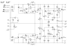
Finally got around to putting together a GG for powering opamps in a DAC. It was spec'ed following the schematic below but tops out at 14v. Ideally, it would be 15v so likely need to tweak a couple of resistor values?

Thanks for the swift reply!
I don't know if I quite understand the calculation for the current. R3/4/5/6 are 8R2. Could mean that at 14V current is ~300mA?
OpAmps are Burson v7v and from the datasheet, it seems they draw as little as 10mA.
Pardon my ignorance ...
I don't know if I quite understand the calculation for the current. R3/4/5/6 are 8R2. Could mean that at 14V current is ~300mA?
OpAmps are Burson v7v and from the datasheet, it seems they draw as little as 10mA.
Pardon my ignorance ...
T1 maintaining 0V65 across (R3//R4)
same, T2 with (R5//R6)
so, programmed current is 0V65/resistor group
say that you have 2 Bursons, sum being 20mA
reg circuit itself is needing few mA to work
programmed current in reg must be Load Iq (Bursons) plus overhead current (burned in Q3, Q4)
in this case, minimal overhead must be at least the same as load Iq
so, programming for - say - 50mA (per each rail, logically)
0V65/50mA=13R
so, say, R3= 22R, R4=33R
same for R5, R6
in case of 4 Bursons, shoot for 80mA of programmed

Thank you, ZM! Perfect explanation for a novice like me.
You are amazingly generous with your designs, knowledge and time.
You are amazingly generous with your designs, knowledge and time.

Nah, I don't buy it 🤣
Somewhere above you hinted to a 5v version for digital ... did that materialize?
Somewhere above you hinted to a 5v version for digital ... did that materialize?
few of them, but different
but, for basics - don't look further than Fig. 9-7 in this: https://www.ti.com/lit/ds/symlink/tl431.pdf
but, for basics - don't look further than Fig. 9-7 in this: https://www.ti.com/lit/ds/symlink/tl431.pdf
- Home
- Amplifiers
- Pass Labs
- Let's discuss ZM's Good Gemini shunt