whichever shake your cage more
that's my personal criteria for all choices

that's my personal criteria for all choices

I was looking for a reg with the lowest output impedance at the lowest possible spare current.
What output impedance has the Gemini reg when you run it with 50ma spare current? What about 100ma?
What output impedance has the Gemini reg when you run it with 50ma spare current? What about 100ma?
whichever shake your cage more
😀 Shake, shake, shake …. K.C. and The Sunshine Band
Some beards shakin' is right for you ZM - ZZ Top
@schultzsch - Salas UBiB 1.3 is what you are looking for.
I have the ubib 1.3 already but it needs 100ma as spare current to have a low output impedance and I was looking for something more efficient.
I have the ubib 1.3 already but it needs 100ma as spare current to have a low output impedance and I was looking for something more efficient.
UBiB build guide specifies 50 – 100 mA over peak load current, so you can go lower.
Anyway, why is efficiency your concern at only several W of dissipation, and why would you need PS output impedance in the uOhm range for a preamplifier? IMO, that alone wouldn’t make any performance difference.
For anyone primarily concerned with efficiency, shunt regulators and A class amplifiers are wrong solutions. 🙂
When you never turn it off it makes a difference. Going from 100ma to 50ma for me means 6w less and if I don’t need to dissipate why to?why is efficiency your concern at only several W of dissipation
I am still learning what is good and useful, since I have the regs off the board and connected with wires these will have higher impedance than the regs.why would you need PS output impedance in the uOhm range for a preamplifier?
What would be recommended as impedance for the shunt for a preamp?
What I wanted was to optimise the power supply of my preamp. I already optimised my class a amp😎For anyone primarily concerned with efficiency, shunt regulators and A class amplifiers are wrong solutions.
You’re funny 😃Beginning to sound like a money no object project or ... 🙂
If you are keeping your equipment always on, then yes, every watt counts. Can we assume reason for always on equipment is perception that it sounds better that way? I don’t ignore fact that everything sounds better to me after several hours of listening. But I assign that to my ears/brain/perception accommodating better, not to my equipment achieving optimal working conditions.
It’s hard to say what is optimal PS output impedance for any preamplifier and that would depend on circuit design. Usual safe bet is “lower is better”. My opinion is that other PS properties like transient response (reaction to fast load changes), noise and rail harmonics generated by PS under AC load, are affecting sound quality more.
You could make a simple check. Add 0.1 to 1 Ω resistors between PS output and preamplifier circuit and listen if you can hear any difference. There will be an answer does PS output impedance really matter in case of your preamplifier.
Good Gemini did splendidly with anything I (and few other guys) did throw at it
say what V and Iq of load is
don't care for Rout, low enough
say what V and Iq of load is
don't care for Rout, low enough
Yes, I keep on the dac and also the preamp.If you are keeping your equipment always on
The entire audio line is dc coupled, the preamp has a dc servo that needs to settle every time I turn on the preamp.
If I forget this for once and turn the amps on right after the preamp I can risk to damage the speakers.
To mention also that the gain stage of the preamp was cloned after a comercial product that doesn’t have a mains switch and the guys who build it recommend to keep it always on.
I didn’t ask them why they recommended to keep it always on when I cloned the gain stage but I do follow the advice 😎
I need 28v and 150ma. Problem is I want to build a full smd version of it. Is it possible?say what V and Iq of load is
of course it is possible
facts:
GG is programmed for ~ 75mA in case of Iron Pumpkin SE, where it is feeding 20mA load ( buffer), and for 100mA in case of Iron Pumpkin, where it is feeding 40mA load ( two buffers)
and - frankly - that overhead is even overkill, no need for that much, but no use of skimping it to negligible levels just to save 500mW of heat; you can see that I'm not even mounting any heatsink to Mosfet shunting elements at all, just on series CCS bjts ....... go figure
same drek you can see in Iron Pre - practically same reg, with minor difference of few resistors replacing few smd aux CCS-es
if you have 150mA load, programming current for GG with enough overhead is in range of 200mA - piece of cake , just matter of proper routing ( observe Iron Pre sshots for example of good enough) and good-enough heatsinking
btw, have in making slightly simplified/different cell of shunt reg for some digitalitis - load Iq in range of 400mA, so programmed current hefty dialed to 600mA, just because I can; heat still not too high, simply because input and output voltages are small thus Delta is effectively not big
just for giggles ( to keep at least some ohms for current programming resistors value) I resorted to TO220 darlington, instead of BD; all difference being fixed value of 1V3 vs. 0V65
and it gives better figures in the end
now, started playing looong ago with regs, when I was a Kido all the rage was with toob stages and I end most liking shunt regs; no reg at all (heavy CRC) worse, but still better than series reg
at least I had ears like that in Yore
later, resorting to multilegged fuses, had my share of investigating various sorts of shunt regs ( yup, even insane Borbely ones, made exclusively of scarce Toshiba JFets and Mosfets) ....... and, same as Pa said about his speaker choice - "I like that my speakers are having at least some magnet" (question about Eminence Alpha 15), I can say - I like that my shunt reg is having at least some gain in error amplifier
of course, phase behavior then became important factor, but rare are the things being easy as lazy walk in the breeze
just remember one thing - sam as with (any) amp, for regz too - pcb strategy and routing is pretty much of same importance as actual schematic
so, in short - GG for 28Vdc and 150mA load is trivial, and it'll work as charm
I can’t say the same thing about my regs.heat still not too high
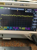
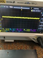
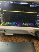
They get 35v on the input and 28v on the output with 260ma current on the ccs for 150ma load.
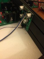
I attached each reg on the lateral panel of a modushop 2u 28cm slim line enclosure and the panel gets pretty warm, I think it’s in the 40-45c range, this with the load connected. Having everything on an aluminum pcb keeps the temp on the pcb components close to that of the heatsink.
Please see the attachment.
So between mosfet, bjt and darlington you say that the best ccs is the darlington one? In terms of psrr?
If you add a series reg in front of the shunt is it worth the extra effort?but still better than series reg
How much?I like that my shunt reg is having at least some gain in error amplifier
Well for this one seems that I have to bother ZM for calculating output voltage, I don’t get much about the phase to be honest.of course, phase behavior then became important factor, but rare are the things being easy as lazy walk in the breeze
To keep the phase ok I guess you need to have a certain amount of current through the ltp? Is too much bad?
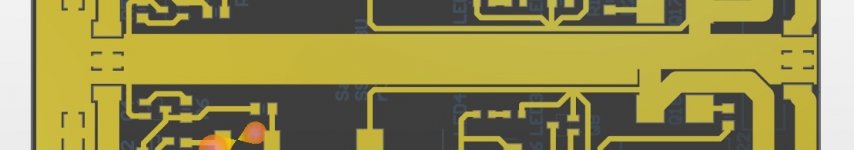
I managed to implement the Salas shunt without having oscillation in the circuit, tested with and without a load. Same as you say, I had to take care about how I routed gnd node and also output node. If interested I can share a print of the pcb. I didn’t get Salas permission to share the gerbers on the forum.pcb strategy and routing
I attached some printscreens of the shunt when powering the load.
hm, let my finish the enclosure of the pre and after I will come back to the voltage regulators.it'll work as charm
Attachments
-
 6201AFDF-D52C-4FE9-B961-5DC20F8B2CE5.jpeg313.5 KB · Views: 155
 -
 5F5544AC-368D-4932-B600-D41F60534981.jpeg475.8 KB · Views: 150
 -
 CDEC62D9-A8A0-438E-9DEF-509B6278658C.jpeg429.6 KB · Views: 144
 -
 61E96EA4-F317-4733-8B50-2082465CEDFF.jpeg463.5 KB · Views: 147
 -
 09BCD3FC-A034-4559-BA1A-F9785585D185.jpeg351.9 KB · Views: 158
if you take a look at GG schematic, be it in Iron Pumpkin or in Iron Pre, you'll get all answers on questions you did ask, and regarding my choices
my stance is - when Reg is properly made, by my personal preferences, it'll result in same sound whatever current overhead you choose; there is no need for 100% or 200% or 300% of overhead ... what I always take care of is possible mains variations of -10%, counting that in necessary input voltage, while - if load is really not capable to leave intended current envelope - even 15-20% of current overhead is enough, practically same as 300% of current overhead, sound wise
I mean - GG is nothing new under the sun, seen myriad of times everywhere
what is, again, important - optimized routing, to separate power traces from sense traces yadayada
anyway, if you chose to make GG on your own, when you ready just buzz, paste here schematic of interest (GG from IP or GG from IP), say your voltage and load Iq
I don't care will you share Gerbers of your own pcb; there is a reason why I post schematics of all my concoctions ....... Pa is doing that from Yore, and see where we are exactly due to sharing of experience and knowledge
properly made meaning with the phase adjusted as you want?my stance is - when Reg is properly made
Salas didn`t give the permission because he has a group buy running with that reg, I do understand him and there’s no problem with me.I don't care will you share Gerbers of your own pcb;
I learned this from Hynes. Many years ago I had bought 2 shunt regs from him. After a while I burned by mistake the ccs of one and sent it back to him for service. After a long waited repair he sent back the reg in a hurry (I guess) and forgot to sand off the part number from the burned part in the ccs(the one that controlls the ccs). His mistake helped me to see the entire ccs part list.what is, again, important - optimized routing, to separate power traces from sense traces yadayada
So I can say that I learned a lot for the price I paid for 2 regs that I sold after a period.
In the attachement is the GND, I used a similar approach for V+ and V-
Attachments
"properly made" - meaning - entire concept and execution made by my own wakoo standards
heck, I can't make things better than I'm able to, but nothing is stopping me to declare it Mighty, as result of my own Mightiness
so, not just phase, but also routing, stability, Rout, heat, all those interdependent things
not to count on fact that I'm insisting on using generic parts whenever I can, so parts sheet is not involving headache while reading it
now, I'm not comparing Salas's reg with mine; didn't test his nor I intend - I made my own just because I can ...... which is probably same exact reason he had ......
I didn’t get yet to build so much stuff to get a big part list but some shoe boxes full of parts did gather around all these years, this mostly because I started to use smd instead pth.
Practically what you say is that a good shunt reg is a good shunt reg and when compared to another good shunt reg there shouldn’t be any noticeable difference, both getting you in the end to Rome.
Practically what you say is that a good shunt reg is a good shunt reg and when compared to another good shunt reg there shouldn’t be any noticeable difference, both getting you in the end to Rome.
There should be noticeable difference being different parts, topology, layout and a few other things. The question would be if the difference matters that much to you. Chasing the bestest of the best of the bests is the money no object project.
yeah, as Mighty Indra sez - good is good, whichever way it's made
though, we know that all animals are equal
yours is to find which ones are even more equal
though, we know that all animals are equal
yours is to find which ones are even more equal
Most of the times I can’t make a difference tbh, I have to trust what I measure and the foot-tapping like ZM says.The question would be if the difference matters that much to you
For me it’s more like an optimised project and a learning experienceis the money no object project
Like I said I am not a good hunteryours is to find which ones are even more equal
- Home
- Amplifiers
- Pass Labs
- Let's discuss ZM's Good Gemini shunt