Grey
Well understood. Helpful and amusing.
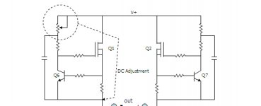
Please remember, two or at least one Rgs is adjustable.
This is to let the DCs at the output nodes face the same value.
And . . .
I will rewrite . . . when the outside weather is cooled down . . . when my head is free from smell of alcohol . . . and when I finish cleaning up my desk for two week holidays . . .
Regards
jH
Well understood. Helpful and amusing.
Please remember, two or at least one Rgs is adjustable.
This is to let the DCs at the output nodes face the same value.
And . . .
I will rewrite . . . when the outside weather is cooled down . . . when my head is free from smell of alcohol . . . and when I finish cleaning up my desk for two week holidays . . .
Regards
jH
I think that F1 is a single stage circuit.
I believe that I could adjust the DC offset rather easily even if I use unmatched gain mosfets. I am considering one of two ways.
(1)
Having one adjustable resistor in the load current source system.
(2)
Or, having one adjustable Rgs.
As Nelson has said many times, I should first adjust dc offset at cold operation condition, then, adjust once again at warm condition.
I think that method (1) would assure me the stable dc offset.
Am I too optimistic . . . ?
Could you please give me wake-up call . . . ?
Regards
jH
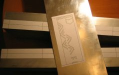
Heat sinks arrived . . .
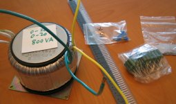
Trafo will come soon . . .
O! I changed mind . . . It will be one 20-0 20-0 800VA, sized 152mm dia and 93mm high . . .
The one remaining thing I am concerned about is whether the gate voltage of the current sink (lower ccs), about 4V, will be stay fixed or not. Here, as Nelson tipped, the stability of the drain Q voltages is a matter. Still I am not 100% sure of . . .
Regards
jH
Attachments

Hmmmm... here goes your wife again😀 I would mount the feets of your amp on the faceplate🙂 Otherwise, you could have trouble dissipating the heat😉Heat sinks arrived . . .
Steen😎
Heatsinks arrived ..........
Hallo jh6you ,
very nice kitchen(Heat)-Sinks
in Class A - Modus you can grilling very easy 2 T- Bone Steaks !
Greetings from Germany
Jürgen
Hallo jh6you ,
very nice kitchen(Heat)-Sinks
in Class A - Modus you can grilling very easy 2 T- Bone Steaks !
Greetings from Germany
Jürgen
jh6you said:
Heat sinks arrived . . .
I see you are not the only one using the kitchen table to brew the amps!!!
Good work jh...
apassgear said:
I see you are not the only one using the kitchen table to brew the amps!!!
Good work jh...
A 100% clone, down to the smallest detail 😀
Magura 🙂
Nelson
I can't understand what are the causes of the unstable dc at drains.
The Vbe varing with temperature in deck ccs could be one reason.
The gate voltage of the bottom ccs must be stable so that it could not be a concern. But, the drain voltage of it could vary, as you say, so that it could be another reason, and probably this would be the most concern.
If so, could I sense the varying darin voltage and cure it in simple way? Could you give me a tip?
Don't say, "you will see it in a month or sooner . . . Muuuuuuhahahahahahaha . . ."
Regards
jH
That hardware is sweet looking! You've just got to love the sight of a rod of IRF's😀Trafo arrived . . .
Almost, "Like a virgin".
I am not sure Mr. Pass is up to revealing the details yet. As I understand from the postings on that matter, you have to wait till the end of this July

Well, you signed the papers, but didn't get rid of me🙄
Thats the way it works😀 😀
Steen😎
Hint: Assuming that you're using a half-way decent CCS, it's not the one under the differential. The voltage is supposed to vary. It's constant current, not constant voltage.
Grey
Grey
steenoe said:I am not sure Mr. Pass is up to revealing the details yet. As I understand from the postings on that matter, you have to wait till the end of this July
Why would I want to spoil your fun?
😎
Steen
You did wrong. Really wrong. Nelson was about to inform some.
But, you made him shut up. You know? I do not trust him much.
His one month could be three months for us. No alimony for you!!!
Grey
Your hint makes me further confused. Hmmm . . .
Ok, I will post my circuit tomorrow . . . because I know mine is
different from the Firstwatt F1. So, it should be no problem.
Isn't it right, Nelson . . . ? I would like to hear all your opinions on
it.
Regards
jH
jh6you said:You did wrong. Really wrong. Nelson was about to inform some. But, you made him shut up. You know? I do not trust him much
to quote the Joker:
Who do you trust? Who do you trust? Me? I'm giving away money! And where's the Batman? He's home washing his tights!

You are giving away! . . . nevertheless, not enough yet!!
I am tired of this hot weather . . .
And now tired of holiday beer . . .
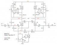
Here is my preliminary circuit.
P1 is to adjust the offset close to 0 at output.
Nelson says in the Zen V7 article: ". . . by a single ended input . . . one input is driven and the other is grounded and we see some voltage swing occur . . . and thus also on Drain of Q3 . . . variations as much as +/-3 Volts . . ."
I think that he developed F1 mainly for tube preamp users, i.e. for the single ended pre. Then, to him, the voltage of variations of +/-3V must have been 😱
For the same reason, I would like to have R23 and R24. This is to make an ac ground at the drain of Q5. If it works as I think, the dc voltage across the bottom ccs could be getting stable.
I wish to hear from you about all kind of comments.
Any give-away-! comment would be appreciated.
Phew . . . I am sweating too much . . .
I need more beer . . .
I will try this circuit until I get the efficient single unit drive . . .
Regards
jH
I am tired of this hot weather . . .
And now tired of holiday beer . . .
Here is my preliminary circuit.
P1 is to adjust the offset close to 0 at output.
Nelson says in the Zen V7 article: ". . . by a single ended input . . . one input is driven and the other is grounded and we see some voltage swing occur . . . and thus also on Drain of Q3 . . . variations as much as +/-3 Volts . . ."
I think that he developed F1 mainly for tube preamp users, i.e. for the single ended pre. Then, to him, the voltage of variations of +/-3V must have been 😱
For the same reason, I would like to have R23 and R24. This is to make an ac ground at the drain of Q5. If it works as I think, the dc voltage across the bottom ccs could be getting stable.
I wish to hear from you about all kind of comments.
Any give-away-! comment would be appreciated.
Phew . . . I am sweating too much . . .
I need more beer . . .
I will try this circuit until I get the efficient single unit drive . . .
Regards
jH
Attachments
JH , do not forget to use smaller input capacitor remember .... you do not want the amp to work too much hard 
And why that R1 R2 so big ....
And why that R1 R2 so big ....
- Status
- Not open for further replies.
- Home
- Amplifiers
- Pass Labs
- Let me lite fire - Nelson Pass F1