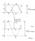
I estimate that 40Vp-p comes . . .
We however might have no chance to climb up that much
because the distorsion in signal would climb up faster. . .
🙂
Regards
jH
I think it's safe to say that a 10W (presumed RMS) amp would deliver something on the order of 20Vp-p.
Look at it this way. The fundamental topology is a differential. To a first approximation, each side of the differential can travel from the absolute DC offset of 13.8VDC up to the rail, and probably a similar distance down. Nelson said the rail is, what, 25V or so? It's in one of the threads, somewhere. For the moment assume 25V. Okay so that means (quick fiddle on a calculator) a little over 11V up and about that same voltage down. Given that it's a differential, both of these are occuring at the same time, just as though two kids were going up and down on a see-saw. Subtract a little for housekeeping for the CCS up top and you'll end up with a number fairly close to the 20Vp-p figure.
That's not to say that you can't scale the general idea up or down, just the way that the SOZ can be ramped up to any arbitrary amount of wattage with big enough heatsinks and output devices. Well, and a beefy power supply, of course.
Anyone want to make a 50W version?
Grey
Damn . . . English is difficult . . .
Every time I can’t remember spelling of chassis . . .
And why it reads /’shaesi/ . . . Terrable ! ! !
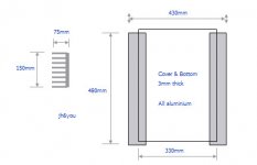
Here is the box dimension I will build soon.
I think I can get the size of heat sinks easily here.
steenoe
I really need to find IRF140 or 240 around here.
At least 10 for one F1. If possible, matched . . .
I do not have the qualification certificate for my soldering skill.
So I always need 50% spare in case. It makes total 15.
Wait a minute . . . I might build two F1s. So, total “30.”
I need to hurry up . . .
Before my wife and sons visit me . . .
My wife tries to stop my diy and smoking . . . for safety and health
(Maybe for saving money) . . .
She never gives up . . . I do not give up yet either . . .
Regards
jH
Attachments
I just read the manual of F2. Could someone help me here?
The key words are "voltage in, current out, no feedback". What it would be like if you make a preamp like F2? No feedback preamp, which its voltage gain depends on 1 final resistor value?
The key words are "voltage in, current out, no feedback". What it would be like if you make a preamp like F2? No feedback preamp, which its voltage gain depends on 1 final resistor value?
Grey
Is it very late night there . . . ? 😉
Or, I am smoking too much . . .
As you says, while "A" side go up to 10, "B" goes down to -10.
So total difference is +20 from "A"'s point of view.
And opposite direction -20. Mmm . . . +/-20 (=40p-p?)
"Why are you making amps again and again . . . You have already enough . . ."
Hmm . . . I have never complained her buying shoes so often and many . . . Listen to me! Even Nelson Pass uses the one and the only shoes, everywhere, inside limo, at concert, and at exhibition . . .
Regards
jH
The voltages don't add that way. It's just the one top-to-bottom value.
Imagine that you are the load. What is the maximum voltage swing that you could ever see? It's either +10 and -10 or -10 and +10. You can't see both at the same time.
Grey
Imagine that you are the load. What is the maximum voltage swing that you could ever see? It's either +10 and -10 or -10 and +10. You can't see both at the same time.
Grey
We are thinking about the same.
You: It's either +10 and -10 or -10 and +10.
You: It's either +20 and 0 or 0 and -20.
😎
Grey . . . Do you know where he is . . . ?
His tonge is tough . . . Particularly to you . . .
So I used to call him Jaws . . .
I remember he is from Texas . . .
Why he is shut up his mouth . . . ?
I read here and sometimes feel boring . . .
Where are you Jaws . . . ?
Regards
jH
Nelson Pass said:the F1 is basically a tarted up SOZ.
Isn't that Elliot's punch line ?
The F2 manual is very enjoyable to read.
I gave my dogs their notice for 10 months from now.
Is the low gain of the F2 not an important factor ?
jh6you said:Suddenly about F2 . . . here . . . ?
Blame Lumanauw !
The F2 manual is a nice addition to the one of the F1, imo.
For one, as it clearly shows how 2d harmonics cancel eachother out on the F1, brilliant.
I used to be schizophrenic but not we are doing better. 😀
I dont want to play it smart here
Well actually you dont add the voltages you substract them.
Voltage is a potential difference.
V1 - V2
10V - (-10V) = 10V + 10V = 20V
I dont want to play it smart here
Well actually you dont add the voltages you substract them.
Voltage is a potential difference.
V1 - V2
10V - (-10V) = 10V + 10V = 20V
Hi!
Nelson, thanks a lot for "uncovering" a F1 schematic. But since I am a guy who prefers a 2-nd harmonic, it seems that I'll have to wait for you to make and sell 100 pieces of F2, in order to get a schematics (maybe in July 2006?)😀
In fact, I think pass DIY community may well know that it has been already uncovered here on forum.
Hence, I don't expect that F2 be something very different than what was posted on a thread "Zen without feedback".
On the other hand, I still believe that there is another rabbit in a hat
For me, the choice is clear: I will build a "no feedback ZEN" as presented on the forum, let it work as it may be, and modify it whenever you publish "the proper version".
Anyway, thanks a lot for your input, comments and hints.
Best Regards,
Viktor
Phew . . .
Make F1 first . . .
Enjoy 3rd harmonic sound first . . .
Tired . . . ?
Go to the kitchen . . .
Bring the scissors . . .
Draw the center line of the F1 . . .
And cut it along the CL into two halves . . .
fold them . . .
Make them in parallel . . .
Add output caps . . .
Now you have F2 . . .
Enjoy 2nd harmonic sound . . .
😱
Regards
jH
The F2 manual does make erroneous reference to "XLR
connector" and refers to the input impedance as being
"balanced" which it is not.
/pass/: makes new manuals by poorly editing old ones.
😎
connector" and refers to the input impedance as being
"balanced" which it is not.
/pass/: makes new manuals by poorly editing old ones.
😎
Thanks, but if my documentation got too professional, the
I would lose standing in the audio community.
😎
I would lose standing in the audio community.
😎
I want to read F2 manual . . .
But, I can’t connect your web site . . .
Too many visitors are in the long queue. . . ? ? ?
Otherwise, me, on the black list . . . ? ? ?
Nelson Pass
If I use 0R22 source resistors, is the inner voltage gain of F1 could be approximated as about 25dB with 8ohm spker? I want to roughly figure out the input impedances for mine. Thanks.
Regards
jH
- Status
- Not open for further replies.
- Home
- Amplifiers
- Pass Labs
- Let me lite fire - Nelson Pass F1