OzOnE, you show appreciable modesty, which i like, but come on, you're a freakin' genius mate 😀
oh how i wish i had something to contribute to what you're working out here, i only hope that some of my physical design ideas can complement the really complex stuff you're doing
so to summarise, i don't have the physics wantons to comment on this programming business, but i'd be really grateful if you have the solutions, 'cos frankly, when it comes to this stuff, i'm a little bit lost
throwit,
Surely if you're using colour filters, you'd be filtering out most of the available light when using white LEDs?
By using an array of red, green and blue LEDS, would you not get maximum efficiency for each LCD panel by bypassing the filters?
By the looks of those pocket projectors, RGB LEDs give an excellent colour gamut too.
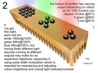
bad terminology again, by pre coloured i meant red, green and blue leds, i agree, probably the best way to go, as you may have seen previously in pictures i've done, you may need different amounts on each channel, as below...
Attachments
I thought so! I just saw the picture, and assumed you'd gone back to using the filters. 😎
I've seen your other designs on this forum and on the other forums. Excellent pictures btw, what software do you use to do the 3d look?
RGB LED's are definitely the way to go as you should get maximum efficiency plus the ability to control the colour balance. RGB is also ideal for DLP projectors (if I can ever figure out this colour wheel software!)
I can get the RGB channels to switch in a pre-defined sequence which means you can set the timings of red, green, and blue to match the proportions of these colours on the original colour wheel. (You can also add white if your original colour wheel has a white section.)
But, there's no simple way of altering the speed as yet, because you'd have to divide down the colour timing values to "fit" the faster wheel rate. I think I might need to use a small second PIC to simulate the virtual colour wheel. The primary PIC then just receives the speed data, and sends a timing pulse to the second PIC.
I'm just designing a PCB board for the PWM controller. I'll probably only use six channels, because I'll move it to a PIC 16F88, which has less pins. This PIC is cheap though, and has so many features on.
I don't know when I'll get round to making the PCB. I find making the PCB boards quite stressful! I don't have a proper PCB drill, so I try to make everything surface mount and single-sided.
thanks about the pictures, they're done with corel photopaint, all you do is draw a mask in the shape of each face (in the case of the heatsink), and virtually airbrush the colours in, being able to 'swap' or invert the mask is dead handy too, and i have to say that no more spitting/clogging/cleaning airbrushes, like you get in reality is a definate plus !...the leds themselves were 'appropriated' from luxeon/futurelectronics' webpage, and rotated and distorted to pretty well look the right shape...and then there's the glory of cut n' paste !...something i make much use of - hail the mighty computer !
no 3d trickery involved, as you can probably tell from my slighty dodgy perspectives !
a graphics tablet and pen are must haves for drawing as well
yeah, i love the idea of being able to skew the colour balance @ the leds (by brightening or dimming a channel individually), very cool, plus, being able to adjust overall brightness at the same point would be ideal, i can imagine being able to leave the projector settings at 50% red, 50% green 50% blue and 50% bright, and doing those adjustments independantly of the projector software
something instinctively informs me that adjusting the brightness at the lamp, will improve contrast, i can't back it with sound theories, i just think it'll turn out that way
as far as pwm controls go for muppets like me, i'd like to see a dial for each channel, like a volume control...if it could be done and would be cost-beneficial, perhaps there could be analogue dial/controls, with rotational travel describing output to obviate the need for output displays...i.e. with the dial turned full anti-clockwise you'd have zero brightness (or close to zero as pwm allows), fully clockwise turned dial being full power*, and midway between the two points 50%
*although it may be important to limit 'full power' to 80-90% max, for led junction longevity
do you think there's an overlap in our requirements - that your dlp pwm led system could use the same pwm led system as a 3lcd like i have ?...that'd be handy
by the way, i would of course be willing to pay you for your skills and anything you construct for me, should it come to that
shame even running the cheapie leds i have isn't straightforward, as my projector (my sole display device for everything) is on its last lamp, which is at 2,100 hours out of a stated 2,000 max !...if i was a little smarter i'd have found out what to do to run the projector (admittedly probably a little dim pictured) using a simple white lamp based on the 40 10mm i have (as a stopgap/leccy saver in the meantime)...have wall socket...have leds...what goes between...err ? !
You know, I never really thought about the projector's own settings for a while there. The PWM would therefore be for fine-tuning of the colour temp, and for overall lamp dimming.
throwit, the example design already has the dials on (potentiometers). This is simulated in software atm, but shows that you can just use simple analog dials to select the PWM duty-cycle / LED brightness.
The only reason to add a serial interface would be to set the PWM / brightness of each channel via a PC, and also to utilize some of the other pins on the PIC for even more PWM outputs. I don't see anyone needing more than about six outputs though, as just one output could be used to control the entire red LED array for example.
Right, this next bit is a bit complex, but here goes....
I've just found a solution for the colour wheel software where a "virtual colour wheel" exists inside the software as a timer which "rotates" one degree for every clock cycle received on a PIC input pin. (well, not actually 0-360 degrees, but 0-255 which is good enough)......
A second internal timer is then used to output a simple clock frequency based on the desired speed variable. This clock is output on a PIC pin, which feeds-back to another pin to increment the "virtual colour wheel" timer. This all means that
1. The desired proportions of red, green and blue (and white?) keep in the proper amounts no matter what "speed" the "virtual colour wheel" rotates!
and...
2. It means that because the timer for the speed calculation is 16bit instead of 8bit, it's closer to the speed accuracy of the original motor driver chip on my projector (and hopefully most other DLP motor chips!)
I just need to build something now and test that the data connection from the projector to the PIC works, which then sets the speed of the "virtual colour wheel" accordingly.
So, the sequence would be......
1. Projector requests motor speed via data bus,
2. PIC chip receives speed request and updates internal speed variable accordingly,
3. PIC simulates rotation of the "virtual" colour wheel at the correct speed (with RGB LED switching at the correct times / correct colour proportions for the given speed.)
4. PIC also outputs pulse signal to the projector's original colour wheel "opto-reflector" to fool it into thinking the original motor is rotating at the proper speed.
There's a great flash demo about DLP and the colour wheel at....
http://www.dlp.com/
Of course, we are trying to replace the projector lamps with LEDs, so why not replace the need for the colour wheel in DLP projectors too? 😉 I for one would love to see the difference in the colour fidelity when using LEDs, not to mention the possible reduction of the rainbow effect, and the much reduced noise.
Problem is, unless I can bypass the "motor OK" signal to the projector, it's difficult to bypass the original motor. It's possible the projector doesn't read the signal from the motor control chip at all, and hopefully just detects the rotation / speed via the "opto-reflector". In which case, the replacer board should work as it is!
I don't know yet if I can apply the principals of the new colour wheel replacer software to the PWM board, but, the PWM board was intended for use on both LCD and DLP projectors (to tune the colour balance of an RGB LED array.)
In other words: You would use a colour wheel replacer board with a PWM board connected after it for DLP projectors. And just a PWM board in LCD projectors.
Oh, and although I said the PWM board currently only operates up to around 200hz, the colour wheel board on the other hand would be plenty fast enough, because it only needs to operate at a few hundred RPM. eg.....
The top speed is around 125Hz : 125Hz means "times per second", but 125Hz = 7500 "times per minute" = 7500RPM !!! (I think that's fast enough)
Unfortunately, I don't think I can get the PWM board to go much faster than about 166Hz for dimming LEDs as yet. I'm sure there's a simple solution though.
throwit, do you still need help with a power supply for the LED's?
Phew, that was a post-and-a-half. I'll try to keep them (a bit) shorter in future.
Ok, I've just tested the pulses to the ballast on the Proxima, as well as the output from the colour wheel opto....
The sync pulses to the ballast must be taken from the colour wheel motor drive pulses, as they start off at 180hz, which is three times the normal wheel speed (60hz). The signal is also quite noisy, with quite a bit of "ringing" on the pulses, so this signal is most definitely from the motor windings.
The opto pulses however are nice and clean (as they should be), and give a direct correlation to the colour wheel speed. The default speed is 60Hz (3600RPM) - this changes to match the incoming video frequency. eg. SVGA at 70hz (4200RPM).
So, the Proxima DS1 has a 1X speed colour wheel, which makes it easier for me to add the "colour wheel replacer" board at a later date. The maximum refresh rate of the Proxima DS1 is 85Hz apparently, which would mean an top colour wheel speed of 5100RPM.
I found that the projector doesn't seem to mind if the opto signal is unplugged. But, if it is unplugged, the motor can't regulate it's speed at all and spins at it's maximum speed (not scary fast, but faster than normal). The question now is whether the DLP chipset timing is governed by the opto-reflector pulses, or by the motor pulses? Hopefully, it works from the opto pulses, as this is MUCH easier to fake.
The other news is, the Proxima doesn't shut down when the colour wheel motor is unplugged! This is strange, as I'm sure it shut down when I tried this before (must have been another connector or power wire loose somewhere).
If the DLP chipset does indeed work by the opto-reflector pulses, the colour wheel replacer should work fine once I get the data bus working for the speed variable!
If this is the case with other projectors, there's hope for this project yet!
("colour wheel replacer"? must think of a shorter name)
more technical issues with this laptop, had wanted to reply earlier - basically it's been the night of flashing red leds here - felt like the laptop and guineapig pj were ganging up on me !...more on that later...
colour wheel replacer seems like a good descriptive name, but maybe shorten it down to cwp to go with dlp/lcd/led/pwm/etc - etc
having read and tried to understand the more technical aspects of your last posts, are you saying that you may be unable to make a cwp equipped pwm-led-dlp (!) run without its colour wheel motor spinning ?...perhaps you could leave the motor in place and running, but just with a bare spindle to quieten it up if nothing else works, or as a stopgap ?...had thought of this as a stopgap measure to make my projector fans quieter
yes please OzOnE, i would appreciate some advice regarding operating these leds
i don't know what i've done wrong, but today i did some things to the projector that may be causing me trouble...the projector now displays a red led flash upon plugging in, i've been wracking by brain trying to figure out what is causing this...i removed the first line of polarising filters and multi lens panes from the light path today, saw no evidence of sensors of any kind whatsoever, or of corresponding sensors on the main board that sits above it (though i could be missing something on the board)...after the red flash, the projector does the green on/off flash for about five minutes, never displaying an image, then goes back to that green/red alternating business it did a few posts back before it actually worked minus the lamp
another thing i've done (but now undone) was to remove the screws that hold the lens/prism/lcd/mirrorbox in place - i had hoped to tilt the whole lot up in the bottom of the pj case, to get a better torch angle...but it never came to that working, because there is now no function in the lcds, and the projector apparently knows something's up 🙁
my biggest doubt and concern is that shorted connector, i thought it would be a good thing cut the two wires, and just twist them together, which i did...but that could be the problem (though i don't know how), thinking this sudden lack of function may have been somehow related to the now shorter cable, a spliced in an short length to increase back to near what it had been, but nothing
really pissed at myself for doing so many alterations at once, as now i don't know which one messed things up
need to strip it completely back down tomorrow in the light of day, could be something stupid and obvious i missed, but i have tried to be thorough and can't see where the problem is
I think I've sorted the software for the CSB (Colour Sequencer Board! no, yes?). The problem is, I can't pick up the data signals between the DLP chipset and the colour wheel motor chip. It might have something to do with the fact that I'm using the PC's sound card as a cheapo oscilloscope (only for low-voltage stuff!!). The sound card is obviously going to be way too slow to capture the data if the data is clocked at many MHz.
It looks like the data bus is the only method used for setting the colour wheel speed (see patents below), so unless I can aquire the data, I'll have to put the CSB project on hold for a while (for the Proxima at least).
I suppose it would be possible to leave the original motor attached then clock the speed from it, but it would be nice to have a neat solution to the problem.
I'm sure that bypassing the colour wheel in a DLP projector would be a huge leap forwards in terms of performance - The image should be brighter, and the colour fidelity should be fantastic when using LEDs.
I found some nice Texas Instruments patents online which actually contain the same A8902CLBA chip as used on my Proxima's Ti formatter board!......
http://www.freepatentsonline.com/5880573.html
http://www.freepatentsonline.com/5625424.html
I only include this sort of stuff here in case it's any kind of help to someone. I get the feeling I'm starting to clog up these threads a bit though. Please let me know if I should put this stuff in another thread.
Regarding your InFocus: I had a similar problem with the Proxima at one point. I had everything the same as before but it would only give a red warning LED for some reason. So, I unplugged all the boards and put them back together, then made sure all the power connections were OK etc. and it just started working again??
Is it possible the Infocus lamp life timer has expired?
There should be absolutely no reason I can think of that shortening the ballast signal wires would cause any problems at all. Did you say the PJ was working for a while with the shorted wires?
It could be that the projector does have the old problem where it's detecting the "lamp on" signal before it's even started up - but this might have meant that your original wire connection was intermittant, and just happened to connect at the right moment after power-on? (can't think of anything else atm)
I've also got a small piece of wire looped into the connector on the Proxima with just some tape to hold it in. I did notice that this is easily dislodged?
thanks OzOnE
so if i disconnect the wires, and touch them together by hand once the projector has fired up, will that be safe ?...it should rule in/rule out that possibility
had used a single strand of copper wire from larger cable to bridge two terminals in connector (now cut off - wish i'd left it alone !), perhaps i should reinstate a short length of the same wire as it did seem to work (seemed securely wedged into both terminals of connector - didn't seem loose - though it could have been, in fact the more i think about it, it seems likely it was intermittent, or loose enough to do both roles)
thanks for the info about the length of wire, strange thing was our bt internet phone cable a while back, didn't work when ext cable was 10 metres, but did work once it had been shortened to 9.5 metres ! 🙄
pretty sure lamp timer is around 600 hours on that pj
csb sounds good
just tried pulling the wires apart and a restart (shaped each half into a hook to re-establish connection), still the same red flash, no good after initialisation either...🤐
The length of cable for these type of logic signals shouldn't make any difference. It's only higher speed data signals that need the cable length to be taken into account.
I'm as stumped as you are on the Infocus then. 🙁 The only sure way to get the timing near enough right is to connect an opto between the "lamp on" pins and "lamp OK" pins.
Did the projector ever work after the wires were twisted together? Did you keep the rest of the wires on the connector?
Quick news update: The signals I thought were just motor noise on the Proxima's data bus were in fact the actual data! I should have realized that the data closely coincides with the opto pulses because.....
The projector monitors the wheel speed and position via the opto, then sends constant speed adjustment data to keep the wheel in sync with the incoming video frame rate. This is just like in the patents, and this should also work with the CSB!
All the projector does to syncronise the colour wheel is to slow it down, or speed it up slightly (from the reference speed) - just like a (good) DJ does with vinyl.
sounds like good news for your csb-dlp-led then if you have that data ?
no, the damned thing never worked since i cut the two wires at the connector (and twisted together), but i can use the other connector (with wire pushed into connector again) from the other projector to test, if nothing else works
i'd just like to say, that whoever decided to make these things function in this unhelpful way is a 🤐 and their 🤐 can 🤐 with a 🤐 until the 🤐 right up their 🤐 ! 😉
just have to hope i spot the glaring and simple oversight tomorry
I honestly don't see how putting the connector on would make any difference. You never know, stranger things have happened with electronics I can tell you.
I hope you get it working again. It sounds like a loose fan connector or some other anti-throwit sensor, as the projector must know about a problem like you said.
Ok, catch ya later peeps. Night for now (or good morning, good afternoon, good evening and good night - dependant on time zone!) zzzzzzzzzzzzzzzzzzzzzz
throwit, I just had a thought....
Maybe your projector IS too clever, and actually detects the current drop on the other two optos when the ballast is plugged in?
I very much doubt this though as it obviously worked before when you just had the wire loop in the connector. It could be a fan problem, or an interlock switch in the lamp housing or the dust filters?
Check that no connectors are swapped 'cos some might use the same number of pins. Also make sure the boards can't short out on any metal chassis and that sort of thing.
It could be something fairly simple because of the flashing lights, but it doesn't say anything about red / green flashing in the LP240 user guide? But it says.....
"If the projector has been working for 2000 hours or more, replace the lamp and reset the lamp timer by pressing Volume +, then Volume -."
(You would have thought the lamp reset would be more complex than just Vol+, then Vol-?)
I don't think it has sensors on the dust filters, it only shuts down if the dust clogs up, then trips the overheat sensor.
hi mate, thanks for thinking of me and having a look into the manual - been doing the same thing here, so much for infocus claims that there is an expanded led indicator page on the website, there ain't no such thing !...have infocus tech freephone number, bloke there says it's the psu...if only he knew how right he was
here's what i was typing when i got email notification of your post...
"confusion level ten...befuddlement factor 9.5 !
i'm really losing my sanity here 😉
okay, so the red light upon plug-in was just a red herring, turns out the standard projector does the same thing, i'd just forgotten was all - sorry !
because i was running my guineapig pj naked, there was no clear plastic led indicator cover, which as it turns out blends the green flash into the red so you don't see the green
it was the damned connector/short cable between one small board and the other with the optos on it !...i'm now looking at a naked pj that has been successfully running without its lamp psu or lamp for twenty minutes
i borrowed the same connector from the standard/complete pj, and stuck in a strand of copper wire again, hey presto - thing's doin' it right again
will follow up with results trying to reuse the now cut connector that was causing me the problems - any ideas what to do ?...cut it shorter, short at connector itself ?
there seems to be some need to leave the connector intact, i have no idea why though !...i may need to source a replacement for the cut connector/cable...definately leaving the good one alone"
the fan's keeping me cool 😀
now i can try to see what image if any, i get with my torch (now charging), a bit later once it's dark, minus the parts i've removed
Hi,
This is very strange indeed. I keep thinking you've plugged the ballast back in, but you're just shorting the connector pins again aren't you?
I'm sure the pinout is correct for the opto board, so it can't be that. Did you cut the whole connector off on the other cable? Are you sure you shorted the first two wires (top of opto board when connector plugged in?)
If you're now using the opto cable from the other PJ but don't have the ballast plugged in, and are just shorting the two connector pins again, I can't see for the life of me why cutting the connector off and shorting the two wires would cause any problems?
Is the opto cable reversible? ie. does it have the same connectors at both ends?
I did think just now that I might have got the pinout wrong on your opto board because I thought it's slightly different to the Philips ballast in my Sanyo....
If you look at the left-hand photo in your post with the opto board....
http://www.diyaudio.com/forums/attachment.php?s=&postid=950605&stamp=1151533004
You can see a vertical trace to the left of the connector. I thought for a moment that this might be different to my ballast, but it's exactly the same.
I tested the pinout on my ballast again just now, and it's correct. I then realized that there's still no way the pinout is wrong anyway, because your PJ is working now with the first two connector pins shorted.
So, unless you've shorted the wrong two pins, or cut the cable at the other end then reversed it, I'm completely at a loss to explain what's going on.
If you look at the two cables, do the two wires you're shorting now connect to the same places on the projector side as the shorted wires on the modified cable?
i know, it's completely nuts !
no ballast, that's sat next to me here
the connector has identical/reversible plug-ins, had thought it may be direction sensitive somehow, but it works whichever way round i use the cable (as long as the correct two pin holes are shorted at the free end)
on the other now useless connector, i cut the two wires to be shorted* just after the ballast end plug, also i cut the middle wire when i tried lengthening it (used middle wire spliced in)...still got it all, but not sure what use it is now
*pretty sure i cut the correct two
must be nearly an hour - still working fine
it would be easiest if i could get you some photos, but due to the cruminess of this laptop (usb used for internet, but goes wrong half the time, and doesn't recognise my compact flash card reader) i need to send any pictures to my pc, then use a memory stick to get them to this laptop , then of course i need the projector on to use the pc 🙄
no ballast, that's sat next to me here
the connector has identical/reversible plug-ins, had thought it may be direction sensitive somehow, but it works whichever way round i use the cable (as long as the correct two pin holes are shorted at the free end)
on the other now useless connector, i cut the two wires to be shorted* just after the ballast end plug, also i cut the middle wire when i tried lengthening it (used middle wire spliced in)...still got it all, but not sure what use it is now
*pretty sure i cut the correct two
must be nearly an hour - still working fine
it would be easiest if i could get you some photos, but due to the cruminess of this laptop (usb used for internet, but goes wrong half the time, and doesn't recognise my compact flash card reader) i need to send any pictures to my pc, then use a memory stick to get them to this laptop
, then of course i need the projector on to use the pc 🙄- Status
- Not open for further replies.
- Home
- General Interest
- Everything Else
- The Moving Image
- DIY Projectors
- LED Projector (YES YOU CAN!)