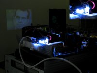
okay, so there's some kind of nicola tesla free energy weirdness going on here, but as long as it's working i'm alright with that
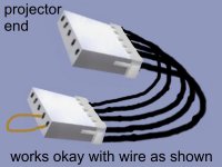
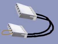
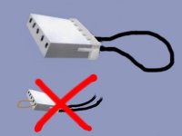
repaired the cut cable/connector by dissecting it and using the two good wires in the important places, as shown below...i'm back in business !
five minutes of normal operation so far
repaired the cut cable/connector by dissecting it and using the two good wires in the important places, as shown below...i'm back in business !
five minutes of normal operation so far
Attachments
Glad you got it working again.
The only explanation I have for it working with the wire loop is that the projector doesn't expect to see a dead-short across the opto pins, and is instead seeing the (very small) resistance of the wire loop.
The projector might have a circuit which was balanced with the normal voltage drop between the emitter and collector of the opto output??? (correct me if I'm wrong).
I'm still finding that sort of explanation hard to comprehend, but that's all I can come up with atm!
The best way to get most PJ's working then might still be to solder an opto between the "lamp on" signals and the "lamp lit" signals. This should give almost correct timing, plus the proper drive for both signals.
i don't know, but it could be that the sparkly elves just like the colour of copper
"The projector might have a circuit which was balanced with the normal voltage drop between the emitter and collector of the opto output?"...sounds like the most likely explanation to me
seriously though, should i now worry about heat issues in that copper strand ?...and if someone was planning on doing this, and as you say soldering the opto and leaving the ballast in the projector, would it still do the tricking if the ballast was not plugged into the power ?
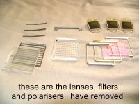
early indications of shining a torch in the projector without the multi lens panes, or uv/ir filters, and without first stage and final stage polarisers are very positive - i was watching horseracing or something on the wall just a while ago, via the gutted pj
reminds me of a doubt i have though, most of what i've been exposed to in the way of specs for leds, says no uv/ir are emitted, but this info has come from the sellers, who would say that, what does any reader of this think wirh regard to tight (visible light only) spectrum from leds ?...or do you think they emit uv or ir, either from new, or as they age ?
"The projector might have a circuit which was balanced with the normal voltage drop between the emitter and collector of the opto output?"...sounds like the most likely explanation to me
seriously though, should i now worry about heat issues in that copper strand ?...and if someone was planning on doing this, and as you say soldering the opto and leaving the ballast in the projector, would it still do the tricking if the ballast was not plugged into the power ?
early indications of shining a torch in the projector without the multi lens panes, or uv/ir filters, and without first stage and final stage polarisers are very positive - i was watching horseracing or something on the wall just a while ago, via the gutted pj
reminds me of a doubt i have though, most of what i've been exposed to in the way of specs for leds, says no uv/ir are emitted, but this info has come from the sellers, who would say that, what does any reader of this think wirh regard to tight (visible light only) spectrum from leds ?...or do you think they emit uv or ir, either from new, or as they age ?
You would not need the ballast to be powered if it just uses optos to give signals to the PJ and you modified the optos to loop back.
There is no direct electrical connection between the ballast signals and the projector's processor boards (this is the whole point of optos). The projector merely detects the light from the LED inside the opto using the phototransistor on the opposite side of the gap.
So, as long as a ballast uses optos, there would never normally be any reason to power the ballast if you could fool the opto signals and timings properly for your PJ.
You also wouldn't need the ballast attached at all if you made a separate circuit with just one opto soldered between the "lamp on" and "lamp lit" signals. (this is what I meant by my opto idea)
You won't have to worry about any kind of heat issues in the copper strand as it's purely a logic signal to a processor, and very little current should flow through it. You should make sure it's not too flimsy though.
I'm still confused by the whole copper strand thing. I've tried both....
1. Soldering the two pins on the "lamp ON" opto together on the Proxima's ballast and leaving the ballast attached...
2. Shorting the two connector pins by poking a strand wire into the connector with the ballast disconnected completely (as I have it now).
Both these methods worked fine for me, so I honestly can't see what the strand of copper is doing on your Infocus
As for the LED question. I'd imagine that LEDs output fairly monochromatic light (single wavelengths) at their specified wavelength as long as they've not been damaged by heat and / or overcurrent.
To get other colours from a single LED, they either combine more than one die in an LED, or combine different chemicals to output more than one wavelength / colour at a time.
A visible LED shouldn't output much IR/UV at all as long as it's working properly.
If you look at the colour spectrum on the following page, there hardly any light produced in the areas which would be considered UV or IR......
http://www.girr.org/girr/tips/tips7/white_led_tips.html
UV-A is specified as anything below about 400-380nm. The first onset of IR is said to be around 700-780nm.....
http://en.wikipedia.org/wiki/Ultraviolet
http://en.wikipedia.org/wiki/Infrared
So, LED's shouldn't output any worrying amounts of UV/IR if it's a visible light LED. This is as far as my understanding goes by looking at the graphs etc. I've never looked into this sort of thing much before, so please don't hold me to anything!
throwit, what are the specs of the white LEDs you have? And what kind of power supplies do you have lying around.
You can modify most modern switching power supplies to a higher or lower output voltage by changing the voltage divider (two resistors!) at the other side of an opto (yes, by coincidence, those critters again).
I'm actually using a modified laptop power supply to power the TFT monitor I'm typing on right now. I modified it from around 16 volts up to 24 volts to run the monitor. I only needed to change one resistor to do this.
So, if you need a higher output voltage for running your LED array from, you might be able to find a nice PSU to modify. It think it would start getting a bit hairy to use once the voltage gets to around 45 volts or more, as it could probably give you quite a bite.
the pj is still working here with the copper strand thing, i'll post some pictures soon
unfortunately, not being an owner of many portable toys such as mobile phones, and having sold my electric bike components and 24v charger, at present i have no power supplies going spare, but i might think of something i've missed, or could buy a cheap power supply or something
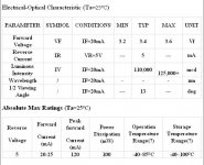
the leds are vf 3.2-3.6 typical 3.4v, 100ma (?), i was thinking of using (4x4) 16 or (5x5) 25 of them, innadequate, but hopefully it'll do for a while
unfortunately, not being an owner of many portable toys such as mobile phones, and having sold my electric bike components and 24v charger, at present i have no power supplies going spare, but i might think of something i've missed, or could buy a cheap power supply or something
the leds are vf 3.2-3.6 typical 3.4v, 100ma (?), i was thinking of using (4x4) 16 or (5x5) 25 of them, innadequate, but hopefully it'll do for a while
Attachments
it all sounds a bit hairy even for this basic lamp...according to this website , i need two 36v power supplies to run 16 leds 😱
Attachments
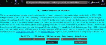
Your LED's are rated at 20ma nominal by the looks of it. The LED calculator at linear1 is much better - it will give suggestions for the resistors to use, as well as how to connect the array.....
http://led.linear1.org/led.wiz
If you start off with 12 volts as your source voltage, you'll notice that you can only do so many LEDs in series (in a row) before you'd need a higher input voltage. So try 20 volts and see what happens for an array of 16 or 25 LEDs.
If you try a 25-LED array, a diode voltage of 3.4V, a diode current of 20ma, and source voltage of 17V, you can see that the resistors are then only 1ohm per row.... The resistors are then only dissipating the last 0.4mw (tiny amount).
If you then up the voltage to 20V, the recommended 150ohm resistors dissipate 60mw (still not much).
So, the closer the total voltage drop across all resistors in a row, the less heat will be wasted in the resistors.
Either way, the calculator is excellent and works pretty much everything out for you.
Here's a twist though: At first it seems difficult to get enough LEDs in a row when the source voltage is only around 12V, but this doesn't quite make sense, because it's only the way the calculator draws the layouts which confuses things.....
In other words, when you try the source voltage at 12V with 16 LEDs, the calculator only draws three LEDs per row. Of course, this doesn't mean you can't organise the LEDs in rows of four, it's just that it would be slightly harder to wire it all up.
thanks OzOnE, you post is clear and informative as usual, but overall i still find the non-OzOnE sourced info bemusing, i also thought that these leds i have were 20ma, but i have successfully run one of them at 82-90ma (100ohm/12v), and all seemed well 🙄
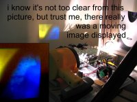
displayed image using crappy torch - blue/yellow some effect of the type of bulb in the torch - i have tried single white leds but as you can imagine, there's not much coming out of the lens with one, but at least it was a neutral colour...unable to photograph as too dim
Attachments
ONE LED? Crikey, it looks like it's not gonna be too bad with an LED array, or with one of those light engines then.
What is the brightness like when the light is on in the room?
Is that just with ONE of those eBay LEDs? What resistor are you using? - 100ohms?
There must have been something simple going wrong with that other cable before. The fact that it works now by sticking the wire in the same pin seems to disprove my wire strand resistance theory (it didn't make much sense anyway!).
I found some 12V 50W halogen lamps today (3 of them for £1.50!). I tried one in the projector, and it's not quite as bad as I thought it would be..... This is only for testing, as I have no lamp or ballast atm, but it looks like it's possibly around 80 lumens (guessing) on a 8 inch image.
hi mate
yeah, just the one running off a 100ohm resistor/12v
the led resistor calculator says i need 22r and 56r resistors, i have some 22r and they're well over the wattage requirement...i have read that leds should not be used in parallel (don't know why though)...the resistor calculator you showed me suggests series/parallel, is this okay ?...if so, then i can run (5-4-5-4-5) 23 off 12volts...it'll be interesting to see how big the image can go then
that photograph was taken an hour and a half before sunset so there was a fair amount of ambient, image was about 8 inches wide
looks like a polariser (linear ?) will be needed in front of each led, if fitted as close to the lcd as possible it will allow maximum recycling of light which is in the wrong plane...of course that'll be unnecessary for dlp
dunno what was happening with the cable, but now of course i have a spare !
in my last post, where i wrote "a polariser (linear ?) will be needed in front of each led", i should have written "a polariser (linear ?) will be needed in front of each lcd
Hi,
I don't know the reason for not wiring in parallel? I think that if an LED blows up and shorts, it could damage the other LEDs in the row?? I don't see how though, as this would short all the LEDs in the line, and the entire source voltage would be put across the resistor instead?
What I do know is, if you wire the LEDs in series and one of them decides to short-circuit, more voltage will flow across the rest of the LEDs in the row and will damage them anyway.
I think the 20mA "nominal" rating on your LEDs is what they would be run at in order to get their average MTBF (Mean Time Before Failure) life rating? I don't think it's a good idea to run them near the peak current rating of 100mA, but maybe 60-70mA is alright??
Strange why the LED needs the polarizer on the LCD projector - As I understand it, the light on the opposite polarization would be blocked (ie. wasted) by the polarizer filter? Do the LCD panels work without using the polarizer in front of the LED?
the led must have been operating at 86-104ma (3.4v typ/100ohm 3w resistor/12v supply) , but contrary to what we'd both expect, it seems quite healthy still after a couple of hours operation
i had originally tried lighting the projector with all polarisers and filters removed (excluding the dichroic mirrors and integral lcd components) to see what the effect would be...but the image was severely washed out like a crt tv on min contrast, then i put one of the three polarisers which had originally been just in front of the lcds in front of the led and instantly there was contrast
so it appears that in the case of a commercial projector, the lcds can only deal with pre-polarised light, omitting this external polariser (or its being damaged by a uhp lamp - or any source of radiated heat such as uv/ir) will result in the lcd being able to function only in a severely impaired way
this is one of the major contributors to light innefficiency...the holy grail, as i've said before, is an led that has a fundamental bias toward emitting light on a single plane, hoping to find such a thing soon
Just found some interesting links on another forum about the Lamina stuff.....
http://led.linear1.org/brightest-led-array-record/
Must have missed that one before! The array is pretty big though - too big for most projectors to use, and probably very expensive too.
The Lamina stuff actually looks like the best candidate for retro-fitting projectors. The BL-3000 series have very high light outputs....
http://www.laminaceramics.com/products/bl3000.aspx
Samsung TV is interesting too.....
http://www.samsung.com/Products/TV/DLPTV/HLS5679WXXAA.asp
- Status
- Not open for further replies.
- Home
- General Interest
- Everything Else
- The Moving Image
- DIY Projectors
- LED Projector (YES YOU CAN!)