hi throwit, I thought it would be an idea to keep in this thread.
I'm only just catching up on some of the other forums - I don't know how you keep up with it all!
So, if you can get roughly 1000lm in the 40mm x 40mm space and get around 350-400lm out, why do the original lamps give out around 15000lm!!?? Is this all down to the narrower angle of projection from the LED's? If this is the case, then all of this might be happening a bit sooner than I first thought. 😉
This is likely been discussed before for ages, but I'm getting lost in what I've seen and what I haven't.
As far as those Luminus PhlatLights are concerned, has anyone managed to get the specs for them yet?
Besides us lot trying this in our projectors, you can be sure the manufacturers will be snapping these beauties up soon, as they will save a huge amount on colour wheels and LCD optics. Not to mention the heat and power savings to the new projector and RPTV designs.
I'd happily invest in some of this stuff to try it out, and mentions of "10 bucks for a Luxeon Flood" makes me even happier!
Blimey it's late / early.... Beauty sleep, more like Shrek.
lol, me too, i've forgotten some of the early stuff i'd learnt, and now can't remember how old i am or what i'm supposed to be doing !
to be honest, OzOnE, i have no idea why the uhp lamps are sooo bright and the image @ lens so dim relatively, but i expect it's a) trying to intimidate the likes of us, b) not strictly true, and c) not a problem as we can cut out more and more of our projectors if we need to, right down to the lcds themselves
i suspect that a lightly modified light engine'll do fine though
i keep meaning to get in touch with luminus, but haven't yet
Which light engine were you looking at? Luxeon Flood etc., or your own design on the heatsink?
I'm gonna order 50 of those LED's from eBay, which ones do you recommended for the highest output? 3mm, 5mm, 10mm? The viewing angle on the Superflux LED's looks way too wide (140deg).
I'm considering getting red, green, and blue LED's instead and try to bypass the colour wheel on the Proxima. That would be fun!
The code to syncronize the PIC + LED's to the colour wheel motor signals will be interesting. In theory, it should be just a case of using one of the motor signals to reset a timer inside the PIC, then dividing this timer value by the different proportions needed for the RGB LED switching. This is assuming the colour wheel motor is three-phase, and the opto feedback can handle an almost instant syncronization from the PIC.
The good thing is, I can simulate this under Proteus on the PC, so I'll get started on that soon.
sorry, might have used wrong terminology there, i meant by light engine: the hall of mirrors between the lamp and the lcds, by lightly modified, i meant possibly ripping out the funny legoland baffle filterydos just after the lamp (from the starting point of an unmodified lcd projector), and removing the uv/ir filters, as well as quite possibly removing the polarisers (on thin glass/metal frame) immediately before the lcds (not integral lcd components - the last ones fitted at the end of the hall of mirrors)
as far as led light sources go, this jury is still deliberating, naturally, the most effective, easiest, cheapest route, or best combination of those three attributes, is my goal ! 😀
...tricky thing with the fancier leds, whether lamina flood, luxeon flood, custom luxeon like my designs, and i assume also the lumina phlatlights, is that i believe they all offer complication with regard to power, and that i have had nothing but conflicting, and mainly useless advice about how you power the damn things ! (and that from those offering the stuff for sale !)
...i have a good understanding of what pwm is - it is serously the way to go if possible - (but it is very expensive - need to find cheap suppliers for pwm - and still offers no extra simplicity), but whatever way you bridge the gap from a 230v wall socket to light coming from the damn things, i've had no luck whatsoever with a straightforward, sensible answer !
i bought 50 of these (and gave 10 away) but to be honest i think the smaller the led, i.e. 3mm or 5mm, assuming the same output can be found as the 10mms i bought, the better - as the metal bits inside are often the same !...i really don't think they're as bright as stated, they'll do for an early effort methinks - i really should bung the 40 i have into my now vacant uhp lamp chassis, but i need advice on a nice and easy way to run them off the mains...or even better, from a parasitic feed off the kettle power input
they're stated as 125,000millicandela (mcd) - does that translate to 12.5lm each, or 125lm each ?...12.5 i can believe based on what i've seen, 125 - no way...looks like proper 100lm leds will be the appropriate solution in the end...i don't mind a feebly dim picture (using what i've got for now) as a stopgap though, what with the finances being as they are and all !
your dlp mods sound cool 🙂

I thought the internals of the LED would be the same. I wonder why the bigger LED's have a higher rating then?
I did a rough estimate of millicandela to lumens by using the converter at linear1.....
http://led.linear1.org/lumen.wiz
The lumens value is obviously the "power density" of the light in a narrow area.
The Luxeon K2's might have 120lm typical per LED, but the viewing angle is around 140deg!
Luxeon K2 datasheet.....
http://www.lumileds.com/pdfs/DS51.pdf
I know the lumens value is impressive, but I wonder if you'd need to use a lens to focus the beam?
The junction temperature can go quite high, which is actually a little reassuring, as I think they'd be fine on a big enough heatsink.
I might be able to help you with the PWM stuff. It's not as expensive as you might think. You just need a MOSFET in line with each array of LED's, and a simple PIC program to control everything. A PIC 16F88 only costs around £4, and could control around 12 MOSFETS! You could easily add a serial interface too, to configure everything. I might get time to work on that sort of stuff and program some chips for you. I've already designed a simple PWM circuit for an earlier project.
I've started on the "colour wheel replacer / RGB LED switcher" btw. I've just got to figure out how to syncronise to the colour wheel motor pulses to the PIC software now.
Edit: lol, nice robot. It's called R3D4 or something isn't it? I'm sure I've seen it somewhere before!
just my little joke
you have just posted one of the most welcome statements i've read in a long time !...but i'm a feeble moron when compared to your obvious intellect...needless to say, me wantee !...but don't expect me to keep up intellectually 😉
pwm is SO cool, whether you end up with a single white led source, or rgb led sources, the opportunity to tune brightness either in terms of colour balance, or picture brightness, is a major benefit
the bulkier leds perhaps allow for a larger cathode than say a 3mm, or maybe it's do to with mimimum side wall thickness or something, but as we've correctly identified, it's the stated output that's of greater importance than size (well, unless the led is as big as above 😉)
yes there are lenses available for those high power leds - shame they don't make these leds for spotlight applications in the first place !
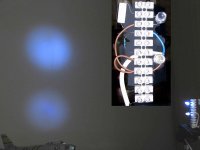
here's a picture of the 'bright spot' generated on my blacked screen image from one of the leds i have...
you have just posted one of the most welcome statements i've read in a long time !...but i'm a feeble moron when compared to your obvious intellect...needless to say, me wantee !...but don't expect me to keep up intellectually 😉
pwm is SO cool, whether you end up with a single white led source, or rgb led sources, the opportunity to tune brightness either in terms of colour balance, or picture brightness, is a major benefit
the bulkier leds perhaps allow for a larger cathode than say a 3mm, or maybe it's do to with mimimum side wall thickness or something, but as we've correctly identified, it's the stated output that's of greater importance than size (well, unless the led is as big as above 😉)
yes there are lenses available for those high power leds - shame they don't make these leds for spotlight applications in the first place !
here's a picture of the 'bright spot' generated on my blacked screen image from one of the leds i have...
Attachments

"I might be able to help you with the PWM stuff. It's not as expensive as you might think. You just need a MOSFET in line with each array of LED's, and a simple PIC program to control everything. A PIC 16F88 only costs around �4, and could control around 12 MOSFETS! You could easily add a serial interface too, to configure everything. I might get time to work on that sort of stuff and program some chips for you. I've already designed a simple PWM circuit for an earlier project"
...i know you cannot see it OzOnE, but i'm drooling uncontrollably here !

...i know you cannot see it OzOnE, but i'm drooling uncontrollably here !
I thought I might add that there may be inherent problems with using PWM with projectors, because the switching frequency needs to be high enough to not cause any sync problems with the image frames on the screen.
Then again, even at a relatively low frequency of 100KHz, you probably wouldn't notice any problems at all.
I've just done a basic design for the colour wheel replacer on Proteus that seems to work for a fixed wheel speed. The real challenge is syncronizing the software to the original motor pulses, and also divide down the rotation time so that the LED's switch at the correct times dependant on the requested wheel speed.
This look more complicated than I first thought, but I've got the datasheet for the motor driver chip now, and I might have to monitor the data to this chip to find out the speed instead. I'd also have to bypass the motor windings with resistors or something.
i'd heard mention that the pwm frequency for leds is in the region of 1000hz, but you say 100khz/100,000hz - sorry i should know these basics, but do you think you need 100,000hz to prevent sync issues ?
i don't know if those leds can go so high - but i'm probably basing this on a misunderstanding of your last post
either way, apparently the high power leds ideally need to switch on and off 1,000 times a second, with i believe a varying length of 'off' time creating the varying brightness
if a projector lcd refreshes less than 100 times a second, then i'd hazard a guess that anything more than 7x higher refresh rate for the leds would be okay ?
not trying to jump in on your dlp modding, and this is probably a poor idea, but if i understand the concept at all, can you not use some kind of mechanical sensing as a driver for the rgb pulsing of the leds ?, kinda like the tdc sensor (which was always failing) on my fiat tipo...i ended up keeping a spare in the glovebox !...maybe you could have three magnetic sensors rotating on a modified colour wheel (i.e. ex-colour wheel - stripped out colour wheel) telling the leds what to do
Probably won't need 100KHz, but I know many newer PWM driver chips use even higher frequencies than this.
It should be possible to modulate most LED's at hundreds of KHz without problems AFAIK. But, I'm sure PWM would work fine at much lower frequencies.
Yes, you're right, it's the on / off time (duty cycle) which determines the overall brightness of the LED's with PWM. The frequency (as I call it), is just the base frequency at which the on /off switching operates.
I did think of a mechanical way of measuring the colour wheel speed. The original wheel has it's own opto for this purpose (as do most DLP projectors). I'm sure I'll figure out the software soon, hopefully without any motor at all.
I'm just wondering how to fake the motor windings though? I don't think the motor drive chip is capable of purposefully "synching" the wheel to a specified position. This is good, because it looks like the processor board just sets the speed digitally, then waits for the opto pulses to match.
The opto pulses then signal the processor to start the colour sequence again. In other words, the processor sets the speed, but the opto drives the RGB(W) colour sequencing (once per rev).
So, it looks like I will have to monitor the data to the motor chip to set the speed of the virtual motor in the PIC software. The PIC's colour switching sequence will then all run at this speed and trigger the opto pulse after each virtual revolution. Phew.
Apart from decoding the data to the chip, this actually might be an easier method than monitoring the motor drive pulses directly. The motor speed is controlled not only by it's switching speed, but also by current control, so it would be difficult to determine the proper requested speed like this.
It's just a shame I won't be able to make a generic colour wheel replacer for different projectors (well, not easily anyway). I'm working on it though.
pwm helps with cooling too as the leds aren't on most of the time they're on 
sounds like you'll be able to do all your driving digitally then by way of the optos ?
i have to say, and it's not blowing smoke, that what you're doing is really cool 😎
sounds like you'll be able to do all your driving digitally then by way of the optos ?
i have to say, and it's not blowing smoke, that what you're doing is really cool 😎
The online calculator gives innacurate results IMO. Those ebay jumbo leds are good for 2 to 3 lumens by my formula. But at 0.99$ per pack of 50 pieces I'd buy 500 or even 1000 of them. Unless I got the price wrong and they're 0.99 per piece!
We want the leds with the smallest beam angle, smallest dimension and best efficiency. The jumbos work out about 36lm/W with my formula, a credible result.
The 40% efficiency applies at best to the bare 3LCDs only. Here's an in depth but worth reading pdf. It also explains the notion of etendue, why they use thousands of lumens UHP lamps, other less known issues.
http://www.iop.org/EJ/S/UNREG/kYHCrhAEWV7Z6t5pQ2dk8A/article/0022-3727/38/17/R01/d5_17_R01.pdf
The close future belongs to sequential DLP with pwm leds IMO. I figure colour wheels use an optical feedback to sync the micro mirrors to the wheel. So intercept that loop.
Nice blue spot pic, throw it. When you do throw that fanless Zalman, throwit on me 😉
ha ha zzonbi - you figured out what my name is all about* !...it all started with a temperamental philips cd recorder - damn thing stopped working, and in reaching the laser to clean it, i realised that 30% of the obstructive framework in the unit could be literally thrown away...well, recycled anyway
it is now my policy to remove as many unnecessary items as possible 😉
nowadays most things i own such as my projector, vcr and pc, are all about easy access and servicing
it is why ideally i'd like to strip as much as possible from my projector, and (money allowing) have led lamps directly in front of each lcd
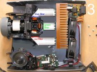
...sorry, that zalman is on my 'good gear, keep forever' list !...and against my zero fan tolerance policy, it is actually fitted with a fan, though it's running very slowly...but if i change my mind i'll let you know !...the picture reminds me i need to vacuum in there soon
very good info, this pdf you posted...says in there a uhp is 10lm/w, and you say 36lm/w even for the cheapie leds i've bought ? cool...by the way, it's the shipping where they charge, but the total price is reasonable...about $20 per 50 leds
*but it's also a good last option if something isn't working - throw the damn thing as hard as you can at the nearest wall ! 😉
it is now my policy to remove as many unnecessary items as possible 😉
nowadays most things i own such as my projector, vcr and pc, are all about easy access and servicing
it is why ideally i'd like to strip as much as possible from my projector, and (money allowing) have led lamps directly in front of each lcd
...sorry, that zalman is on my 'good gear, keep forever' list !...and against my zero fan tolerance policy, it is actually fitted with a fan, though it's running very slowly...but if i change my mind i'll let you know !...the picture reminds me i need to vacuum in there soon
very good info, this pdf you posted...says in there a uhp is 10lm/w, and you say 36lm/w even for the cheapie leds i've bought ? cool...by the way, it's the shipping where they charge, but the total price is reasonable...about $20 per 50 leds
*but it's also a good last option if something isn't working - throw the damn thing as hard as you can at the nearest wall ! 😉
Of course you won't throw that cooler unless you'd get a CPU that doesn't require one at all, which is unlikely. I am a minimalist too, but I have the lids mounted to my PC case (after I finnaly bought a case lol)
I think the 10lm/W mentioned in the beginning of the paper refer to the overall efficiency, ie light on screen/power from AC outlet. The UHP lamps themselves float at around 60lm/W. The collected light is only 65% of that, again 70% pass the colour balancing, 40% the LCDs and 90% the lens, so with this product only a small fraction finnaly reaches the screen.
If we'd manage to greatly reduce the first two losses the leds retrofit suddenly doesn't appear as alien any longer, given that many diy projectors hover in the 100lm region anyway. My mockup projection only spits 1 or 2lm, and I tell you it's not really that awful. Before I had the RPTV lens I had even less, with colours hardly visible. Human eye is a wonderful machinery.
lol i do use the cover on the pc !
but some day i'm going to make myself a ceramic case
so, if i get you correctly, sticking pre-coloured leds directly in front of the lcds would give you a 36% light efficient projector ?...that's more like it !...for the sake of nice round numbers, if you've got 1,000lm total, and well directed led light, then you'll have a 360lm @ lens projector...that's the kind of target which seems both achievable and desirable
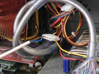
the picture below shows my lp250 with all unnecessary things removed, and led lamps, i thought it might be easiest to mount all channels on a single heatsink, and use ordinary mirrors on the red and blue channels, of course i could move the lcd/prism/lens further back in the projector, this would allow placing of each led lamp directly in front of its lcd...but i'm not sure which is preferable - give the light some chance to 'straighten itself out' as in the picture below, or bunging the leds almost touching the lcd panels ?...of course, if the leds are very close to the lcd panels, that doesn't give you much height and width for an array, another reason i thought doign it as in the picture may be preferable...those phlatlights would stick in front of the lcds a treat though wouldn't they ?
but some day i'm going to make myself a ceramic case
so, if i get you correctly, sticking pre-coloured leds directly in front of the lcds would give you a 36% light efficient projector ?...that's more like it !...for the sake of nice round numbers, if you've got 1,000lm total, and well directed led light, then you'll have a 360lm @ lens projector...that's the kind of target which seems both achievable and desirable
the picture below shows my lp250 with all unnecessary things removed, and led lamps, i thought it might be easiest to mount all channels on a single heatsink, and use ordinary mirrors on the red and blue channels, of course i could move the lcd/prism/lens further back in the projector, this would allow placing of each led lamp directly in front of its lcd...but i'm not sure which is preferable - give the light some chance to 'straighten itself out' as in the picture below, or bunging the leds almost touching the lcd panels ?...of course, if the leds are very close to the lcd panels, that doesn't give you much height and width for an array, another reason i thought doign it as in the picture may be preferable...those phlatlights would stick in front of the lcds a treat though wouldn't they ?
Attachments
Hi everyone,
OK, so I'm getting more enthusiastic about using LED's.....
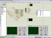
I've designed a basic PWM circuit around a PIC chip.... At the moment, I have four PWM outputs working and can probably go to eight or more with no problems....
The speed isn't too great at the moment, so the highest switching frequency I can get when using 20MHz crystal is only around 200hz. This would likely cause problems with sync on projectors, but this is a work in progress at the moment and just to see if I could do simultaneous PWM in software.
If you wanted a higher frequency, you might be better off with a dedicated PWM chip. The PIC chip does offer things like a serial interface and ADC's etc.
I've attached a screenshot of the design. You can see the four separate PWM waveforms on the oscilliscopes. The duty-cycle on these outputs are set by the four potentiometers connected to the ADC channels of the PIC.
To add the other PWM outputs, you'd need some way of setting the duty-cycles on each output. Once I've added the serial routine, you would be able to set all the duty cycles via the serial port to a PC. The PIC would then store these values in non-volatile memory (EEPROM) for when it next powers up.
This would be ideal for colour balancing with an RGB LED array.
You don't necessarily need the potentiometers, it's just an example of how they would work. The serial interface work of course give ever-so-slightly more accuracy, because the duty-cycle values would then be digital. Potentiometers wouldn't really drift more than "1 notch out of 256" anyway.
The LED's in the screenshot are also just for testing. The idea being that you'd put a MOSFET on each channel, then use each MOSFET to switch (dim) an array of LED's.
MOSFET's can switch fairly huge amounts of power, but you'd need a small heatsink on them.
Any suggestions for the PWM board are welcome. I'm not an expert on this stuff by any means, and many of the ideas for the software routines are from Interwebnet sites.
What would anyone want to add to the PWM board? Would most people be happy with just serial control, or would it be an idea to add buttons to control the PWM outputs? You could a small LCD screen, but this is slight overkill, and would add to the costs.
OK, so I'm getting more enthusiastic about using LED's.....
I've designed a basic PWM circuit around a PIC chip.... At the moment, I have four PWM outputs working and can probably go to eight or more with no problems....
The speed isn't too great at the moment, so the highest switching frequency I can get when using 20MHz crystal is only around 200hz. This would likely cause problems with sync on projectors, but this is a work in progress at the moment and just to see if I could do simultaneous PWM in software.
If you wanted a higher frequency, you might be better off with a dedicated PWM chip. The PIC chip does offer things like a serial interface and ADC's etc.
I've attached a screenshot of the design. You can see the four separate PWM waveforms on the oscilliscopes. The duty-cycle on these outputs are set by the four potentiometers connected to the ADC channels of the PIC.
To add the other PWM outputs, you'd need some way of setting the duty-cycles on each output. Once I've added the serial routine, you would be able to set all the duty cycles via the serial port to a PC. The PIC would then store these values in non-volatile memory (EEPROM) for when it next powers up.
This would be ideal for colour balancing with an RGB LED array.
You don't necessarily need the potentiometers, it's just an example of how they would work. The serial interface work of course give ever-so-slightly more accuracy, because the duty-cycle values would then be digital. Potentiometers wouldn't really drift more than "1 notch out of 256" anyway.
The LED's in the screenshot are also just for testing. The idea being that you'd put a MOSFET on each channel, then use each MOSFET to switch (dim) an array of LED's.
MOSFET's can switch fairly huge amounts of power, but you'd need a small heatsink on them.
Any suggestions for the PWM board are welcome. I'm not an expert on this stuff by any means, and many of the ideas for the software routines are from Interwebnet sites.
What would anyone want to add to the PWM board? Would most people be happy with just serial control, or would it be an idea to add buttons to control the PWM outputs? You could a small LCD screen, but this is slight overkill, and would add to the costs.
Attachments
I mentioned using LED PWM IC's in the previous post, and here are some datasheets to two candidates....
Texas Instruments TLC5940 - 16 Channel LED Driver And Grayscale PWM Control.....
http://focus.ti.com/lit/ds/symlink/tlc5940.pdf
Maxim - MAX6966 / MAX6967 10-Port Constant-Current LED Drivers and I/O
Expanders with PWM Intensity Control
http://pdfserv.maxim-ic.com/en/ds/MAX6966-MAX6967.pdf
You would need a PIC to control these though, but it should be simple enough (famous last words!).
I'm not sure what the maximum switching frequency on these chips are yet.
- Status
- Not open for further replies.
- Home
- General Interest
- Everything Else
- The Moving Image
- DIY Projectors
- LED Projector (YES YOU CAN!)