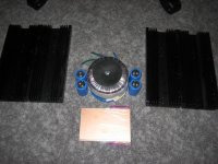
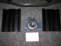
Here are a few pictures for reference of my heatsinks. This is one rail of one monoblock, so there are four sets like this. I know it will get hot, but I do plan to make the majority of the enclosure out of perforated steel or aluminum and use fans as suggested. C'mon, it's just Texas. Average summer ambient temp - 102 degrees fahrenheit 😎
Blair
the le class i built averages 230W continuous dissipation. the heatsinks are ~50*482*151 mm and they run at about 40C above ambient so if it is 20 degrees inside it will run at approx 60 degrees C
maybe a little less.
It is hard to tell from the pic... but i would suggest maybe you will have some heat issues at 370W - perhaps if you let us know the dimensions or the degreesC/W rating i can help
-Dan
Last edited:
Hello Dan,
My heatsinks are roughly: 40mm X 292mm X 115mm each, but each one of these will only have one TO-3 transistor on it. I assume by looking at your figures that you included both of your heatsinks?
Each rail per monoblock will essentially be: 40mm X 230mm X 292mm and have two TO-3 devices on them.
I'm unsure of the heat transfer rate since they are surplus out of some kind of industrial machinery by Murata. I tried my best to resource more of them or at least some figures, but came up empty handed. I am also not opposed to adding more aluminum or a few small heatsinks to the inside of my sinks.
Thanks,
Blair
Hello Dan,
My heatsinks are roughly: 40mm X 292mm X 115mm each, but each one of these will only have one TO-3 transistor on it. I assume by looking at your figures that you included both of your heatsinks?
Each rail per monoblock will essentially be: 40mm X 230mm X 292mm and have two TO-3 devices on them.
I'm unsure of the heat transfer rate since they are surplus out of some kind of industrial machinery by Murata. I tried my best to resource more of them or at least some figures, but came up empty handed. I am also not opposed to adding more aluminum or a few small heatsinks to the inside of my sinks.
Thanks,
Blair
Hi Blair, Very deceptive photo 🙂
for one T03 per 40*230*292mm sounds alot better 🙂
my dimensions were for the whole heatsink ! 🙂
-Dan
Member
Joined 2009
Paid Member
Depending on chasis design, safety and a host of things I can't think of ---- can you mount the TO-3's without any pads. It means that the heatsinks will float at the collector voltage. But the thermal resistance will be lower by quite a bit I think ?
Hi Blair, Very deceptive photo 🙂
for one T03 per 40*230*292mm sounds alot better 🙂
my dimensions were for the whole heatsink ! 🙂
-Dan
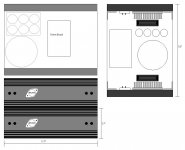
Hopefully this will help with a visual. There will actually be two TO3s per 40*230*292mm. I amp in hopes that the fans will help cool the sinks enough.
I have the mica insulators, and mounting sockets for the TO3s. I think this is probably the best way to mount them. Do you use transfer compound with the mica insulators?
Thank you,
Blair
Attachments

Depending on chasis design, safety and a host of things I can't think of ---- can you mount the TO-3's without any pads. It means that the heatsinks will float at the collector voltage. But the thermal resistance will be lower by quite a bit I think ?
I suppose I could do this, but I'd prefer not to for safety reasons. It is not out of the question, but a little shift on the internal chassis structure of not bolted properly could end up in some spiffy fireworks in my living room. I kind of like my house🙂
Blair
Member
Joined 2009
Paid Member
could end up in some spiffy fireworks in my living room
Good point, I think it's safe to say that this would be unlikely to increase the WAF 🙂
Here is a thought since heat is the main topic of conversation here. Look at the attached drawing. Adding additional heatsinks to the inside of my heatsinks and fan cooling the fins of those would help quite a bit I would think. It adds a little cost to the build, but if I like these and end up keeping them, I do not want to underbuild them.
Thanks,
Blair
Thanks,
Blair
Attachments
some times it helps to do a mock up with out casing the amp to get a feel for the heat involved and weed out potential issues
-Dan
-Dan
OK,
I ordered the boards from Skycoral, and ordered 22v 400vA trannys for these a few days ago. I'm looking at the PS, and I see that it uses a 338K for the regulation. Is this the best regulator for this supply? I will definitely need to sink it.
Also, the graph I used recommended a 22v secondary for 23v rails. Using the 1.4X rule of thumb, I get 30.8v after rectification. is it wise to shunt 7v to the ground in the supply? Why does this graph reccommend 22v instead of a 18v where I would just be regulating 2.2v or so to get my regulated 23v rails?
I hope this question makes sense?
I'm thinking it may be wise to use 25v rails instead and only drop 5v instead of 7.
Any suggestions?
Thanks,
Blair
which board was this ?
for a typical regulator you will need some voltage head room
if you are runing (just and example) 2A current draw from your amp with a 30.8V dc rail after rectification/smoothing you are looking at 17.6W lost in the reg.
which "graph" is it ?
-Dan
for a typical regulator you will need some voltage head room
if you are runing (just and example) 2A current draw from your amp with a 30.8V dc rail after rectification/smoothing you are looking at 17.6W lost in the reg.
which "graph" is it ?
-Dan
SkyCoral.com » PCB for JLH Class-A Amplifier
The Class-A Amplifier Site - JLH Class-A Update
The first link is the board I purchased, and the second one is the article that has the chart at the bottom I used to base my transformer secondary voltage. I ended up buying pretty beefy trannys for this project.
Blair
The Class-A Amplifier Site - JLH Class-A Update
The first link is the board I purchased, and the second one is the article that has the chart at the bottom I used to base my transformer secondary voltage. I ended up buying pretty beefy trannys for this project.
Blair
They Look Like excellent boards.
I have built the 1996 Version of the Jlh which is essentially the same apart form the transistors in the new one.
The LM338 supply designed by williams hart audio is great however it really should be used with either "LM338K T0-3 steel case" for two amp modules or one board for one module with large heatsinking if you use a TO-220 LM338
The higher rail you use (which the amp can handle safely) which still allows the regulators to function correctly will give the lowest loss in the regulators and most power available for the amplifier.
i would suggest setting the supply up once you have completed the amp and then adjusting the voltage to the best you can achieve whilst maintaining low ripple.
-Dan
It does, and more to the point. Thank you! I did not even think about adjusting them after I built the amps!!
Blair
Blair
Are you planning to make your own pcbs?
I'm planning to make my own. Will tracks using a sharpie pen on the blank pcb work with ferric chloride?
I'm planning to make my own. Will tracks using a sharpie pen on the blank pcb work with ferric chloride?
- Status
- Not open for further replies.
- Home
- Amplifiers
- Solid State
- Le Monstre vs. Parallel JLH class A?