Can you please let me know what software you used and
the process for etching?
In fact, i'm going to send you a pm.
the process for etching?
In fact, i'm going to send you a pm.
Member
Joined 2009
Paid Member
In short, yes.
I have all the parts to load my boards. I purchased a pair of 400 vA 18v toroids (going with unregulated supplies), Purchased 1/8" bottom plate, 1/8" perforated top plate, and .25" back panel. I'm going to build the front panel out of exotic wood. I also got 30,000uf per rail for each monoblock.
I ordered my boards, but I am at the mercy of waiting until they arrive from Malaysia.
Here is the kicker. I'm a speakerless audiophile right now😱, so I vowed not to build these until I finish my speakers in the garage. They need about 10 hours before they are done.
Blair
Thought some of you may be interested to see my interpretation of the JLH amp.... It's in use nearly all day everyday and has given no trouble (yet...). It sounds superb and is used in preference to a gain clone, MF A370, rebuilt and modernized Leak Stereo 20 valve amp and various other contenders.
It gives approx 25W RMS per channel into 8R but is currently in use with my 4R KEF speakers so more like 12W in this application. The speakers are 93dB/W though so no problem volume wise!
It gives approx 25W RMS per channel into 8R but is currently in use with my 4R KEF speakers so more like 12W in this application. The speakers are 93dB/W though so no problem volume wise!
Attachments
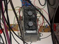
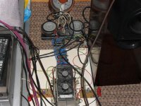
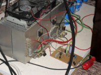
It's a large beast of an amp, about 4' from the variac to the end of the heatsink! Those caps are 14 x 22000uF....
The heatsink stands on spacers giving about 1/2 inch gap around the bottom, the twin fans suck air up and expel upwards.
The heatsink stands on spacers giving about 1/2 inch gap around the bottom, the twin fans suck air up and expel upwards.
Looks Awesome!! What transistors are those?
I take it you do not have small children or pets😉
Blair
I take it you do not have small children or pets😉
Blair
Member
Joined 2009
Paid Member
Those photos are making my fingers itch to build again. I'm gonna have to build one myself too. Probably a more recent incarnation of the JLH but still a JLH. It's gonna be my winter project. I'll use left over parts so I'll be limited in power by the transformers & heatsinks I have to around 6W into 8R, but a good starting point nonetheless !!
Thanks for the erm... positive feedback guys.... Ill try not to oscillate!
The design used is the updated, direct coupled one by Geoff Moss/Tim Andrew from The Class-A Amplifier Site - JLH Class-A Update
There are a few changes of my own to transistor types, mainly because the ones I used seemed to offer good as or better specs than the ones in the schematic but mainly 'cos I had them to hand!
I used the "fig 1 The penultimate circuit" but there may have been some further small changes made.... it's a few years since I built it so can't remember every tiny detail!
The transistors I used are as follows:
Q1,2 = 2SC2987
Q3 = 2SD863
Q4 = BC560C
Q5,6,7 = 2SA844
Q8 = 2SB527
Feedback capacitor is a 470uF Oscon and input cap 2uF mill.spec GEC polypropylene (dont ask 😉 )
I have not tried the "no feedback cap version" but I see I fitted it to pins on the perf board to allow it to be easily tried...
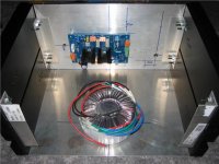
Each transformer has its own 35A bridge, transformers and bridges are mounted to a piece of alloy.
After the first 4x 22000uF caps, there are 0.33R 11W wirewounds which form an rc filter (turnover point 4.3Hz) in conjunction with the remaining caps and remove any annoying residual noise on the psu.
The design used is the updated, direct coupled one by Geoff Moss/Tim Andrew from The Class-A Amplifier Site - JLH Class-A Update
There are a few changes of my own to transistor types, mainly because the ones I used seemed to offer good as or better specs than the ones in the schematic but mainly 'cos I had them to hand!
I used the "fig 1 The penultimate circuit" but there may have been some further small changes made.... it's a few years since I built it so can't remember every tiny detail!
The transistors I used are as follows:
Q1,2 = 2SC2987
Q3 = 2SD863
Q4 = BC560C
Q5,6,7 = 2SA844
Q8 = 2SB527
Feedback capacitor is a 470uF Oscon and input cap 2uF mill.spec GEC polypropylene (dont ask 😉 )
I have not tried the "no feedback cap version" but I see I fitted it to pins on the perf board to allow it to be easily tried...
Each transformer has its own 35A bridge, transformers and bridges are mounted to a piece of alloy.
After the first 4x 22000uF caps, there are 0.33R 11W wirewounds which form an rc filter (turnover point 4.3Hz) in conjunction with the remaining caps and remove any annoying residual noise on the psu.
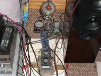
Oh yeh.... The variac!
The toroids I had to hand (about 400VA each) would have given excessively high rail voltages from the 240V AC mains input so I used a variac....
This also allows the power output to be optimised for different impedance speakers, I.E. wind up the supply voltage and back off the quiescent current for higher impedance loads and vice-versa for lower impedance loads.
As noted earlier though I never actually bothered to reset it for my 4R KEF's because it went loud enough already so I thought "leave well alone"
Blair.
Your quite right... no small children or pets around! Mind you it never stopped me when there was... much to the chagrin of my (now ex 😱) girlfriend !
I have a theory that just as plumbers tend to have dripping taps, electronic engineers tend to have amps with no lids/case (what if I want easy access to change something?... or decide to rip it to bits and make something else 😉)
and possible accessible high voltages to keep visitors guessing....
I have a long history of this and nearly decapitated the postman with an errant short wave aerial when about ten years old!... 34 years later and I'm no better! At least the new girlfriend hasn't complained....yet... 😀
LOL!!
Nice! I have a 8.5 month old. I'll have mine covered! Before that, there may be 600v @ 1A on a bare wire in my living room. My wife won't touch anything in there.
Blair
Nice! I have a 8.5 month old. I'll have mine covered! Before that, there may be 600v @ 1A on a bare wire in my living room. My wife won't touch anything in there.
Blair
Member
Joined 2009
Paid Member
I have a theory that just as plumbers tend to have dripping taps, electronic engineers tend to have amps with no lids/case (what if I want easy access to change something?... or decide to rip it to bits and make something else
Scarily accurate - my last amp sat in my living room with no cover, bare wires from the Toroid secondary within easy reach. In fact I've since removed it for safety reasons and it sits unused whilst I work on my next project !
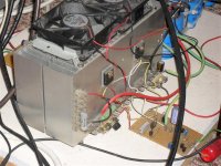
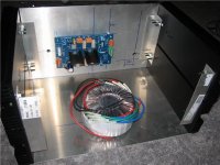
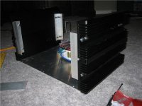
Here is a little progress on my amps build. It is taking forever since I now have a 10 month old son to entertain most of the day!
I still have one panel to drill and two IEC holes to cut and file. 1/4" aluminum, so it should be a pain in the rear! I have the PS filter caps, etc. They will mount on either side of the power tranny. The front panels are going to be solid wood with 50W Class A laser etched in them. Should look pretty sweet!!
Just an update. The other one is a bit less complete😱
Blair
Attachments
We need to convince Jim to host an audio getogether, like he does once
a year for the Robots... If nothing else, you might ask to leave your box
there for a weekend or two? So others passing through can admire the
workmanship.
a year for the Robots... If nothing else, you might ask to leave your box
there for a weekend or two? So others passing through can admire the
workmanship.
Hi Ken,
I agree that it would be nice if we could do that. Jim would probably be OK with it, but we need indoor space. If his warehouse has a large open area, then maybe we could talk him into it. There is a group of us that get together roughly every two-4 months and share beer and DIY projects. Send me a PM if you want my email, and next time we get together I'll send you an invite.
Also, do not forget the LSAF this year. It is always a blast.
Blair
Do you think these are sufficient for a sinlge channel? That is all I'm worried about.
Thank you!
Blair
Thank you!
Blair
OK guys,
Now comes the part where all of you fall out of your chair laughing! I finished, or at least close enough one monoblock today. It looks very nice. I pulled the rail fuses from my PCB, and slowly brought up my rails on a variac. +/-26.2v. Good deal!
Now for the joke. I have never built a SS amp before. All tube gear. How do I adjust VR1 and VR2 for the proper current? Here is the link to the board I used.
Thank you if anyone can explain this to me!
SkyCoral.com PCB for JLH Class-A Amplifier
Blair
- Status
- Not open for further replies.
- Home
- Amplifiers
- Solid State
- Le Monstre vs. Parallel JLH class A?