LOGDSP.EXE with the -t switch displays that the DSPs initialized, sync line: done, memory (A) 64k at 000000, memory (b) 64k at 000000+400000 and all tests done
In some modes, I do get some relays clicking.
In spectrum analyzer mode with the generator set to sweep mode, it's displaying "waiting for cal ana offset", indefinitely.
Right now, I've an external signal generator feeding the input, the UPL being in spectral FFT mode. I've traced signal okay up to the first ADC chip.
I've got a 20V RMS sinewave input connected to input 1. I'm tracing the signal. Test points as follows:
P4 = 1.8V RMS sine
P6 = 40mV RMS sine
P5 = 80mV RMS sine
P7 = square wave, rail to rail
P2 = 3V RMS sine wave
I note that auto ranging function is not operational. I manually set the range to 10V RMS to get unclipped waveforms for tracing. The analyzer does not seem to responding to start commands, other than the screen displaying "started" or "stopped". No relays clicking in response to input signal variation. If I set the range manually to 3V and then switch to AUTO range, the gain remains on 3V and clips the waveforms (actually, they appear triangular and slightly clipped when overloaded).
I'm afraid the damage from that one incident has caused pretty extensive damage to multiple sections of the UPL. I'll continue to pursue fixing generator section, but it is likely that there are problems in the analyzer, and not the analog front end, but deeper into the digital side, as it does not respond to the UI.
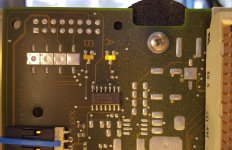
On the digital board on the top side of the UPL there are these two LEDs "A" and "B" only the a LED is lit. See attached photo.
Attachments
Last edited:
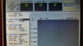
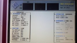
As you can see here the input RMS and frequency functions report 'off' condition even though they are unable to display RMS in decibels and frequency. So it does seem that the UI does not communicate with the analyzer. You'll also notice that it says "wait for Cal ana offset."
Attachments
Last edited:
Service manual Vol 1 reading
I do not have ready answers for you but maybe it is worth to do some manual reading.
Service manual Volume 1
3.3.1.1 Diagnostic Mode
and
Chapter 4
Theory of Operation
and of cource
Chapter 5
Repair
5.1.3 Error Messages and Sates
...page 5.10 Gen Overload LED state at startup ?
I do not have ready answers for you but maybe it is worth to do some manual reading.
Service manual Volume 1
3.3.1.1 Diagnostic Mode
and
Chapter 4
Theory of Operation
and of cource
Chapter 5
Repair
5.1.3 Error Messages and Sates
...page 5.10 Gen Overload LED state at startup ?
Last edited:
Its very possible that the Generator is required to self Cal the unit...
Really, don't mess with the UPL any more until you first fix the generator - better go step by step then risk damaging the unit.
Really, don't mess with the UPL any more until you first fix the generator - better go step by step then risk damaging the unit.
Looking at the schematics it seems the analyzer is open loop. No self nulling and the cal cycle would be essential then. I'm surprised it doesn't show an error message on startup if the generator is not working.
Its performance is exceptional especially since its not using any really exotic parts or difficult to implement techniques. However there sure are a lot of 5534's in it.
Its performance is exceptional especially since its not using any really exotic parts or difficult to implement techniques. However there sure are a lot of 5534's in it.
LEDs "A" and "B"
I did not find any explanation for the LEDs "A" and "B". I traced them to schematics page 28 and 29.
LED A is DSP A LED H1
LED B is DSP B LED H2
Both connected to the DSP chip I/O pins. Best quess some sort of DSP status / heart beat indicators.
About the front panel Gen Overload LED.
How does it behave. Maybe the broken gen gives false overload status and the shop stays closed.
Last edited:
Overload protection
Had couple beers here and did some schematic reading.
Schematic page 92 (blatt nr 17+) are the overload comparators. For measurement/test there are also jumpers X24/X25.
COMP signal goes to schematic page 94 (blatt nr 19+). Important circuit is at mid top around flip flop D39. This flip flop acts immediately to the overload condition and directly clears all the relays. Overload signal GENINT goes to X1 pin 15. Looks like signal name cganges to GINT.
Signal goes to digital unit page 33(blatt nr 16) MUX D8.
So please check D39 pin 5 level. High = Ok, low = over current -> shop closed.
It looks like the output of the comparator is low, because it's not seeing any signal from the generator at the sampling points. That of course makes pint 1 of D39 low. Pin 3 & 4 are high. Pin 4 toggles low momentarily when pressing the generator on/off button. Pin 5 toggled high momentarily when this happens.
The Gen Overload LED is not lit. I've never seen it light, ever.
I am going on the theory that malfunction of the generator keeps this circuit in it's inhibit state.
I have a hunch that 1audio's theory explains why the analyzer is in a halted state and is the theory I've been banking on from the start. Although R&S told me that the analyzer is independent of the generator. However, having failures in both would be really bad luck.
Parts are on order to rebuild generator output and the attenuator, where resistors blew out.
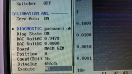
Going to look into that diagnostic mode discussed in the manual.
The Gen Overload LED is not lit. I've never seen it light, ever.
I am going on the theory that malfunction of the generator keeps this circuit in it's inhibit state.
I have a hunch that 1audio's theory explains why the analyzer is in a halted state and is the theory I've been banking on from the start. Although R&S told me that the analyzer is independent of the generator. However, having failures in both would be really bad luck.
Parts are on order to rebuild generator output and the attenuator, where resistors blew out.
Going to look into that diagnostic mode discussed in the manual.
Inhibit overload detector
While you are waiting parts easy test would be to ground both X24 and X24 comparator inputs and see what happens during boot and start measurement event.
While you are waiting parts easy test would be to ground both X24 and X24 comparator inputs and see what happens during boot and start measurement event.
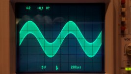
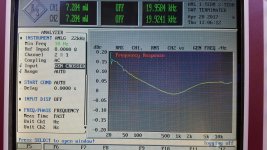
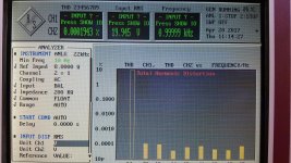
I was thinking of shorting those jumpers to ground just to trick that circuit and that was a good idea that did allow the generator output to turn on. However it appears that the oscillation from the bad op amp is mixing into both generator outputs because there is 348 kilohertz of RF riding on top of the audio waveform. Distortion is pretty high. So it looks like both channels of the generator are used even when only one channel is Switched on for the output. I tried setting up the analyzer for gen crossed mode and I am able to get harmonic Distortion readings so the analyzer does appear to be functional. At this point it appears that the damage is indeed confined to the generator output section and if I can fix it properly and get good enough quality components hopefully the Distortion performance will be on a par with what it was before the incident happened.
Attachments
Last edited:
On both my UPD's that popped here, the Output protection current sense transistors where also damaged so will need replacing - otherwise the UPD (L) will indicate output trip (not allow to enable Gen Output).
I was thinking of shorting those jumpers to ground just to trick that circuit and that was a good idea that did allow the generator output to turn on. However it appears that the oscillation from the bad op amp is mixing into both generator outputs because there is 348 kilohertz of RF riding on top of the audio waveform. Distortion is pretty high. So it looks like both channels of the generator are used even when only one channel is Switched on for the output. I tried setting up the analyzer for gen crossed mode and I am able to get harmonic Distortion readings so the analyzer does appear to be functional. At this point it appears that the damage is indeed confined to the generator output section and if I can fix it properly and get good enough quality components hopefully the Distortion performance will be on a par with what it was before the incident happened.
I'm a little lost here,where are you seeing the oscillation?
I can only say I doubt 99% that the op-amp is damaged - if its on the Generator output then there is damage to the Gen output stage somewhere NOT the Opamp. A blown driver or somesuch which has slowed down the output stage current buffer.
What is the designation of these current sense transistor?
I'm seeing the oscillation at the output of N82. Signal is clean up to that point. It's possible that some other component downstream is causing it. I will replace the transistors and see if the oscillation stops before replacing op-amp.
I'm seeing the oscillation at the output of N82. Signal is clean up to that point. It's possible that some other component downstream is causing it. I will replace the transistors and see if the oscillation stops before replacing op-amp.
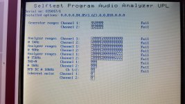
Can now run self test.
Attachments
Last edited:
Mark,
Is N82 the opamp driving the damaged output stage (I'm not sure which channel is damaged)? if so then for sure you will see oscillation as N82 feedback is taken from the output stage.
V84 and V87? (I cannot read the schematic) are the output current sense transistors
Is N82 the opamp driving the damaged output stage (I'm not sure which channel is damaged)? if so then for sure you will see oscillation as N82 feedback is taken from the output stage.
V84 and V87? (I cannot read the schematic) are the output current sense transistors
small good news is that you have now "engine running". Much easier to do the fault finding that with completely dead unit.
Meanwhile I try to understand XL600 circuit. Some oddities found immediately like R301 5R PTC between chassis and 0-rail. Also stereo-mono switch shorting other input whwn in bridge mode. Some strange tuning capacitances at Q102 and Q104 gates.
Meanwhile I try to understand XL600 circuit. Some oddities found immediately like R301 5R PTC between chassis and 0-rail. Also stereo-mono switch shorting other input whwn in bridge mode. Some strange tuning capacitances at Q102 and Q104 gates.
- Home
- Design & Build
- Equipment & Tools
- LCD Backlight for Rohde & Schwarz UPL?