I'm curious to know what level of stereo separation crosstalk I should expect on the UPL? With external jumpers, I'm getting about 92dB of channel separation measured from 20-20,000Hz. I thought it would be more than that, frankly. Has anyone else tested the crosstalk on their UPL?
BTW, I informed R & S that I had successfully repaired my UPL and they wrote me back to say that the analog board is no longer made and if they need to have one repaired, they may be sending them to me for repair.
BTW, I informed R & S that I had successfully repaired my UPL and they wrote me back to say that the analog board is no longer made and if they need to have one repaired, they may be sending them to me for repair.
UPL crosstalk
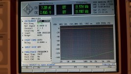
Please define exact test conditions: Bal or unbal, load impedance, gnd ref, "zero CH" open or shorted, analyzer settings etc. Explain or pictures from the screens.
Then I can do comparable measurements.
Please define exact test conditions: Bal or unbal, load impedance, gnd ref, "zero CH" open or shorted, analyzer settings etc. Explain or pictures from the screens.
Then I can do comparable measurements.
I think I found the problem. It was a problem with a custom setup that I used to measure the response of FM tuners and the separation crosstalk between channels. The range was set to manual and 3 volts period when I set it to auto the separation increased to about a hundred and 20 decibels are better. In this mode there is no option to ground or float the analyzer.
When I use the RMS select function I can get the crosstalk figures down to almost - 150 decibels. Then it gradually degrades as you get towards 20 kilohertz to about minus 115 decibels. So I think it was just an anomaly of the test setup.
When I use the RMS select function I can get the crosstalk figures down to almost - 150 decibels. Then it gradually degrades as you get towards 20 kilohertz to about minus 115 decibels. So I think it was just an anomaly of the test setup.
Attachments
UPL crosstalk
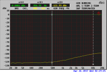
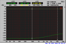
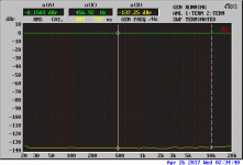
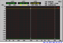
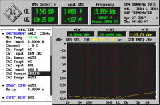
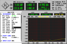
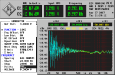
I made test with external loop back cables. Gen 10V, balanced in/out, AC.
Screen 1 and 2 are with 200k input impedance.
Screen 4 and 5 are with 600ohm input impedance.
In Z 200k test it did not matter if I disconected only one end or both ends of the loop back cable.
I made test with external loop back cables. Gen 10V, balanced in/out, AC.
Screen 1 and 2 are with 200k input impedance.
Screen 4 and 5 are with 600ohm input impedance.
In Z 200k test it did not matter if I disconected only one end or both ends of the loop back cable.
Attachments
What happens if you set the analyzer to GEN CROSSED instead of BAL?
The first two traces look like my results.
The first two traces look like my results.
The reason why I'm suspicious of crosstalk is because I'm testing a receiver now with a problem in the left channel. At about the 1 watt level, there's an RF bubble on the waveform. I've found out, using a spectrum analyzer, that the RF is about 1.8MHz.
When this bubble appears, the distortion in the right channel readings bumps up by an order of magnitude. To make sure it wasn't crosstalk in the receiver, I disconnected the dummy load from the left channel of the UPL, and noticed that the right channel distortion readings decrease drastically. The difference goes from .2% to .01%. So the distortion from the left channel is affecting right channel readings. Perhaps this is because of the RF riding on the audio, but I don't remember seeing crosstalk like this in the UPL in the past.
When this bubble appears, the distortion in the right channel readings bumps up by an order of magnitude. To make sure it wasn't crosstalk in the receiver, I disconnected the dummy load from the left channel of the UPL, and noticed that the right channel distortion readings decrease drastically. The difference goes from .2% to .01%. So the distortion from the left channel is affecting right channel readings. Perhaps this is because of the RF riding on the audio, but I don't remember seeing crosstalk like this in the UPL in the past.
UPL crosstalk
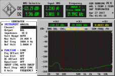
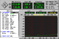
I just made some more tests. Screen 7 & 8 are one internaly connected to the gen and another floating. Screen 9 same + CH2 common to GND instead of float. Makes no real difference.
Plot 0 &1 are both analyzer chanels internaly connected to the gen but gen ch1 or ch2 enabled separately.
Do you have scope picture about your RF oscillation problem?
Attachments

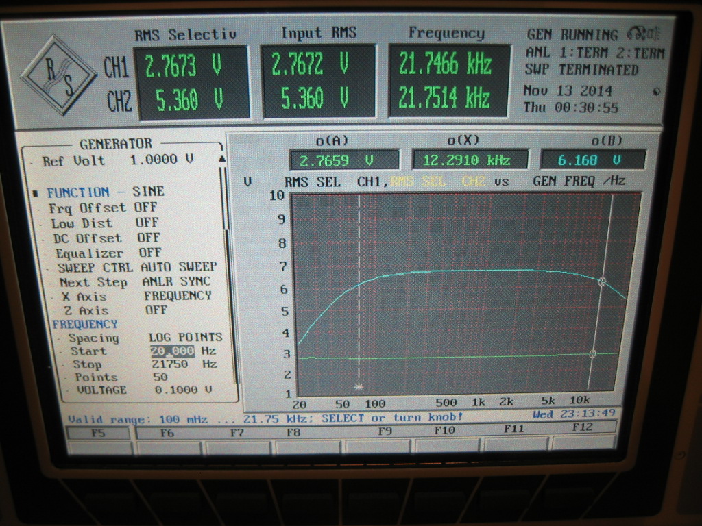
UPL crosstalk & responce
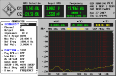
Reducing gen level to 10mV brings above 1kHz crostalk / noise down little bit.
BTW how does your gen -> analyzer flatness look? Here is 500 point sample with gen set to 0.3V. Other setup like in earlier tests. Internal gen to analyzer connections.
Reducing gen level to 10mV brings above 1kHz crostalk / noise down little bit.
BTW how does your gen -> analyzer flatness look? Here is 500 point sample with gen set to 0.3V. Other setup like in earlier tests. Internal gen to analyzer connections.
Attachments
If I take the RF out of the equation, crosstalk seems much better. I tested an amplifier with one channel being driven into and out of clipping, while observing the other channel on the UPL. The "control" channel remained at a constant distortion level, regardless of whether the other channel was clipping or not.
So it appears that the 1.8MHz RF bubble that was riding on the audio output provided a "carrier" which could cross into the other UPL channel. Absent this RF bubble, the distortion levels in the two channels behave completely independently.
So it appears that the 1.8MHz RF bubble that was riding on the audio output provided a "carrier" which could cross into the other UPL channel. Absent this RF bubble, the distortion levels in the two channels behave completely independently.
Not trying to hijack a thread, but I've not been able to figure out how to a simple
frequency sweep from 10kHz through 45kHz.
I've been trying for days, using manual etc. Its a R&S UPD. The vertical scale is
in dBv or Volts and the horizontal is Frequency.
My set ups don't look much different than yours.
The only sweep that seems to work for me is an FFT.
And when it does that, I see the Frequency being sweeped
across the range but can't seem to get just the sweep of
the Fundimental.
I'm trying to make a frequency response curve of a bandpass
filter, with fL 15kHz and fH 30kHz. Those would be the
standard 3dB down points. The center frequency would be
22.5kHz.
It shouldn't be this hard, but it is.
Pics at six,
If the generator has an upper limit of 21.75KHz, that would be the limit of sweeps.
For bandpass filter testing, I prefer to use a spectrum analyzer with a tracking generator.
For bandpass filter testing, I prefer to use a spectrum analyzer with a tracking generator.
That still sounds like overkill. A good function generator and even an analog meter can tell you most of what you would ever need to know about a fixed bandpass filter. A vector network analyzer (Bode 100 https://www.omicron-lab.com/bode-100/product-description.html) can show more but nothing you couldn't figure out with a lot less.
Mark, yes, I realized that I couldn't use the 22kHz generator after it gave me error messages, so it was the 110K generator. Still there has always been something funny
with this UPD, that I can't figure out.
Setting up sweeps 10kHz to 40kHz and viewing it, then changing one parameter,
forget which exactly, but then it would sweep at 10Hz to 40Hz?
Demian, yes I know. But it is always nice to have a few pics of a nice
analyzer in a report. Which was my goal. Arrrg.
Mark, during use, does your UPL stop and calibrate itself?
I've got a smattering of pics, but have to read to the kid.
Now she's even starting to lecture...go figure.


Cheers,
with this UPD, that I can't figure out.
Setting up sweeps 10kHz to 40kHz and viewing it, then changing one parameter,
forget which exactly, but then it would sweep at 10Hz to 40Hz?
Demian, yes I know. But it is always nice to have a few pics of a nice
analyzer in a report. Which was my goal. Arrrg.
Mark, during use, does your UPL stop and calibrate itself?
I've got a smattering of pics, but have to read to the kid.
Now she's even starting to lecture...go figure.
Cheers,
Last edited:
UPD Screens
Shown above in post: #134, my little girl, Tiffany Teacher.
She has mastered the square wave and is teaching our class.
She demonstrates both time, T=1/f, and Frequency F=1/T
Understanding. Not bad for a 3-1/2 year old kid.
Plus she giggles alot.
When the adults don't understand her,
she breaks out in deafening screams and crying.
Here is what I finally ended up with:

From this DUT the 15kHz to 30kHz bandpass filter:

Then, if you go back to the first pic of this series you'll see it didn't
even work? That I can't figure out why not. It is what it is.
The input for the bandpass filter is about the middle right, attached to silver mica.
The output for the bandpass filter is the lower right, attached to the thumbwheel,
used as a rheostat.
The common/ground connection for input output is the lower middle, connected
to the 100K resistor and .001uf capacitor.
I'll post the screens settings I used to my blog, but they are
included in my picture library if interested.
They are supposed to look something like this:
15kHz, 100kOhms
High Pass Filter
30kHz, 0.001uF
Low Pass filter
Shown above in post: #134, my little girl, Tiffany Teacher.
She has mastered the square wave and is teaching our class.
She demonstrates both time, T=1/f, and Frequency F=1/T
Understanding. Not bad for a 3-1/2 year old kid.
Plus she giggles alot.
When the adults don't understand her,
she breaks out in deafening screams and crying.
Here is what I finally ended up with:
From this DUT the 15kHz to 30kHz bandpass filter:
Then, if you go back to the first pic of this series you'll see it didn't
even work? That I can't figure out why not. It is what it is.
The input for the bandpass filter is about the middle right, attached to silver mica.
The output for the bandpass filter is the lower right, attached to the thumbwheel,
used as a rheostat.
The common/ground connection for input output is the lower middle, connected
to the 100K resistor and .001uf capacitor.
I'll post the screens settings I used to my blog, but they are
included in my picture library if interested.
They are supposed to look something like this:
15kHz, 100kOhms
High Pass Filter
30kHz, 0.001uF
Low Pass filter
Last edited:
Just now I do not have good example picture but this old one give you a glue.
http://www.diyaudio.com/forums/atta...1418171314-velleman-4040-rebuild-img_2203.jpg
If you like to draw filter or amp responce use selective rms measurement. It is the same view what you would get with SA and tracking gen (this is it)
"UPL stop and calibrate itself" if you mean DC offset calibration you can control it from the settings if it happens or not during measurement.
I think that to test the response of a filter, you need to have the generator tracking the analyzer. The screen shot above shows an FFT analysis of some discreet signals, which don't really give much clue as to the filter response.
Sweeps above 21.75KHz would require the Low Distortion Generator option B1. Even the noise function of the standard generator cuts off before 22KHz.
I notice that if I chance CERTAIN parameters, that the UPL changes a bunch of other params to some 'default' value. Such as changing from 22KHz to 110KHz Analyzer mode. The Parameter Link menu might have something to do with this behavior, but I have not explored it to much degree.
This UPL, when left to sit idle for some time, will apparently do some internal calibration routing. At least, I think that's what happens when some relays inside click in sequence after some span of time like 5-10 minutes.
@ Oh2, that is exactly what I would like to plot.
I'll try to configure it that way. I"ll try to use the
Selective RMS measurement, that must be code
for .707*Vpk.
Mark, agreed, the plots I ran didn't do much for filter analysis and
while it might be in the manual somewhere, I couldn't find it.
So I'm glad I asked here. I was going to start going through other
R&S models and look through application notes or specific measurement
documentation for it. Selective RMS Measurement just isn't obvious to
me...
If I knew how to properly read and comprehend...All those years ago
I shouldn't have looked at the answers for the school,s SRA Card reading program.
Read about it here, SRA. LINK
Cheers,
UPL responce plot example
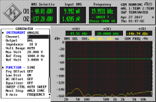
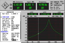
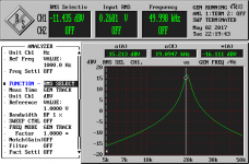
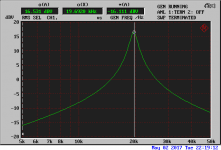
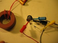
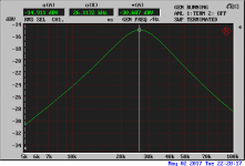
Here you have two examples of LC resonance circuit response plots. First is 4.7mH || 15nF fed via 10k resistor. Calculated resonance 18.955kHz, measured 19.6. Second example lower Q iron core about 940uH and 47nF cap. From the pictures you should get some hints how to set GEN and ANALYZER. You can freely set display scaling, units log or lin scale etc according to your needs.
Selective RMS is band pass filter set to track the generator frequency. Same as synchronously swept receiver. This setup is the same as earlier mentioned SA and tracking gen. Only difference is that generator is swept here and the receiver or detector tracks the generetor with certain bandwith. There are plenty of details involved and here. I can say that the well written operators is your best friend in this matter.
Attachments
- Home
- Design & Build
- Equipment & Tools
- LCD Backlight for Rohde & Schwarz UPL?