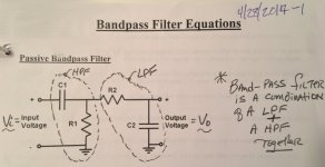
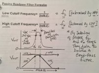
I did find out that when placing a high-pass filter in series
with a low-pass filter especially when limiting them to
using only resistors and capacitors, that they won't
work correctly. There is that low pass filters
resistor to ground with affects the high
pass filter (the first one).
Looking into making
and active bandpass
now.
with a low-pass filter especially when limiting them to
using only resistors and capacitors, that they won't
work correctly. There is that low pass filters
resistor to ground with affects the high
pass filter (the first one).
Looking into making
and active bandpass
now.
Post Script:
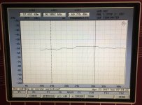
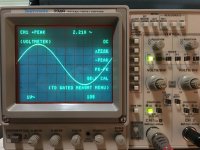
Eventually I discovered when placing two filters in series, they function
slightly different that just one filter. So while I finally got the R&S UPD
to function properly, the result was different than the simulated Bode plot.
It is shown here at the Un-Band Bandpass Filter.
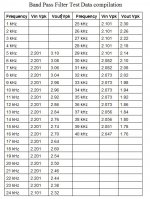
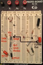
Making a change to the initial capacitor
resulted in these measurements in the Band Pass filter Test Data Compilation.
I think it almost worked, but the data act as though there was no
high pass filter, or perhaps it just shows the resonance
and steadily decreased.
Vin pk, Vout pk, taken with HP/Agilent 34401A.
Verified with Tek 2246MODA Scope
Eventually I discovered when placing two filters in series, they function
slightly different that just one filter. So while I finally got the R&S UPD
to function properly, the result was different than the simulated Bode plot.
It is shown here at the Un-Band Bandpass Filter.
Making a change to the initial capacitor
resulted in these measurements in the Band Pass filter Test Data Compilation.
I think it almost worked, but the data act as though there was no
high pass filter, or perhaps it just shows the resonance
and steadily decreased.
Vin pk, Vout pk, taken with HP/Agilent 34401A.
Verified with Tek 2246MODA Scope
Attachments
-
 Un-band BandPass Filter.jpg237.8 KB · Views: 350
 -
 01.01 AC Filter Ops.jpg87.9 KB · Views: 329
 -
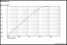 01.01.01 HiPass.2000pico.JPG70.2 KB · Views: 333
 -
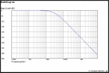 01.01.01 LoPass.001u.JPG67.7 KB · Views: 323
 -
 01.02 BandPass Diagram.jpg43.5 KB · Views: 314
 -
 01.01 Filter Calculations.jpg80.9 KB · Views: 178
 -
 01.02 FilterInput Proof.jpg109.3 KB · Views: 175
 -
 01.01 AmpFilterCallouts.jpg204.4 KB · Views: 178
Last edited:
This is not anymore very much UPL/UPD related but I let it go here.
For simple RC filter you need low Z drive and Hi Z load to get the ideal filter response. Low and high are relative to the filter component reactances.
UPD 5 ohm Gen and 200k load are good for playing. When you connect two RC filters in series you need buffer amplifier in between. For your tests unity gain opamp will do this job. Happy learning.
73 oh2nlt
Thanks oh2nlt.
Here is a final post, I tried to explain it in my blog.
I'll start another thread for that and some other topics.
link to blog here: http://www.diyaudio.com/forums/blogs/synctronx/1424-jfet-amplifer-filter-project.html
cheers,
Here is a final post, I tried to explain it in my blog.
I'll start another thread for that and some other topics.
link to blog here: http://www.diyaudio.com/forums/blogs/synctronx/1424-jfet-amplifer-filter-project.html
cheers,
I picked up one R&S UPL 3years ago 。with B1,B2 optins。soft 2.02。I cannot download the lastest 3.06 soft from network。Could someone please give me the 3.06 soft firmware ,and service schem?
My email:cskg2037@163.com。
Best Regards。
My email:cskg2037@163.com。
Best Regards。
If people are interested in the service manual, i scanned it in once and have a pdf readily available.
The same as for the software. Both DOS and the upl software.
I replaced the backlight with a ledstrip, easy to install and 12volts is coming in from the old backlight. Remove the high voltage converter and you’re done.
The same as for the software. Both DOS and the upl software.
I replaced the backlight with a ledstrip, easy to install and 12volts is coming in from the old backlight. Remove the high voltage converter and you’re done.
Hello ,
I and a friend of mine , we both have and use UPL , are very interested in software and service manual . If you can do this , I think it will be also interesting for many other UPL users here .
Kind regards , Alexander .
I and a friend of mine , we both have and use UPL , are very interested in software and service manual . If you can do this , I think it will be also interesting for many other UPL users here .
Kind regards , Alexander .
Here you go. A bit of a collection of usefull software and documents.
R&S UPL Audio Analyzer - Google Drive
i'm currently designing a custom professional keyboard PCB to replace the broken flex keyboard. This time with tactile switches (for my pleasure). Will post soon with some pictures.
Cheers Bart
R&S UPL Audio Analyzer - Google Drive
i'm currently designing a custom professional keyboard PCB to replace the broken flex keyboard. This time with tactile switches (for my pleasure). Will post soon with some pictures.
Cheers Bart
Last edited:
For all those interested,
I’m listing up all upgrades i performed on my analyzer. Others are free to do so as well.
https://www.diyaudio.com/forums/equipment-and-tools/353461-rohde-schwarz-upl-audio-analyzer-renovation.html#post6178935
Kind Regards,
Bart
I’m listing up all upgrades i performed on my analyzer. Others are free to do so as well.
https://www.diyaudio.com/forums/equipment-and-tools/353461-rohde-schwarz-upl-audio-analyzer-renovation.html#post6178935
Kind Regards,
Bart
Last edited:

- Home
- Design & Build
- Equipment & Tools
- LCD Backlight for Rohde & Schwarz UPL?