Yes, probably best to keep it there.
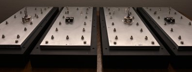
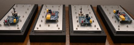
With the assembly so far I can mount the "heatsink modules" (which is now in one piece) when PCBs/SIT/MOSFET has been mounted.
With the assembly so far I can mount the "heatsink modules" (which is now in one piece) when PCBs/SIT/MOSFET has been mounted.
when I was a kid, came to one particular idea very often - what would happen if I sharp 90 turn my bicycle bars, while going full speed ........
and, once I did it
remember - I was pretty skilled then , how to fall properly
....................

What a coincidence. Although it was not something I thought of often, I did think of it once and I tried it. The crash was immediate. Luckily no damage was done although it was painful.


What will happen if you do it on a MC? ......I have no but I have noticed that ZM has at least one?
Maybe ZM do like this if he is a bit sleepy in the morning instead of a cop of coffee?
After this you will probably be fully awake.......
Maybe ZM do like this if he is a bit sleepy in the morning instead of a cop of coffee?
After this you will probably be fully awake.......
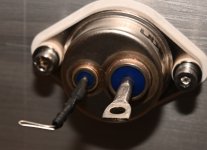
The "small" transistors have been mounted. Although the THF51s is not final secured as it needs extra connection at Drain. But MOSFET (IXTN170P10P in my case) has been secured using my new torque wrench (1.5 Nm). A thin layer of heat paste was applied.
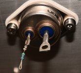
On SIT PCB there is a GATE solder pad and is also marked with a "X" on schematic. It is the junction between ZDSIT and R16. Should I consider this as a probing pad only for testing?
On SIT PCB there is a GATE solder pad and is also marked with a "X" on schematic. It is the junction between ZDSIT and R16. Should I consider this as a probing pad only for testing?
Attachments

pcb is made for direct bolting on IXYS puck, and then G pad is not used, neither S pad (fat wire going to other pcb directly from S bolt of IXYS)
when you're using SIT instead of IXYS, then you're taking thin wire from G pad, with SIT gate resistor soldered directly on Gate pin of SIT (and heatshrinked)
S pad on pcb - thin wire going to Source pin of SIT, from there fat wire going to lower (MU) pcb
GND from PSU connected directly to SIT Drain pin , thin wire from there going to GND pad on pcb
I see........I soldered in R16 on PCB. That was an error I assume. I guess I can let it "SIT" (it will not harm anything?) and then just use another resistor directly on SIT gate?
The gate PIN on SIT has a kind of solder connector attached. I just solder resistor to that? ........heatshrinked.....do you mean using flex isolator that shrinks with heat?
The gate PIN on SIT has a kind of solder connector attached. I just solder resistor to that? ........heatshrinked.....do you mean using flex isolator that shrinks with heat?
leave that resistor on pcb, no harm
yes, gate stopper directly soldered to G pin of SIT (however factory made it, live with it)
then use "flex isolator that shrinks 50% with heat", fully containing G pin, resistor and then some of wire
that way you're increasing mechanical durability of said concoction
yes, gate stopper directly soldered to G pin of SIT (however factory made it, live with it)
then use "flex isolator that shrinks 50% with heat", fully containing G pin, resistor and then some of wire
that way you're increasing mechanical durability of said concoction
Ok, will do that.
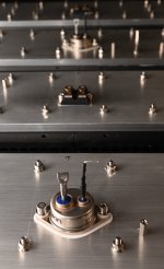
Can see you use a small heatsink also on IRF510. I may have a "clip-on" I can use for that.
Can see you use a small heatsink also on IRF510. I may have a "clip-on" I can use for that.
I believe you have enough info on pics in original thread
no need for heatsink on mosfet
need for heatsink on Q1, BD transistor

no need for heatsink on mosfet
need for heatsink on Q1, BD transistor
A little further progress. Think I soon can mount the heatsink panels to the chassis.
I need to work a bit more on SIT source and drain. Source needs a long thick wire to go to the other PCB at the other side. Drains needs three wires as far as I can see. A thin to GND at SIT PCB and then two thick wires. One for PSU GND and another for Speaker return. Good to prepare as much as possible before panels are mounted as space inside chassis is a bit limited.
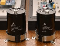
Reason I did not mount any large output caps at PCB is that I have found two caps that needs chassis mount as close to PCB as possible to I can use short wires. Those larger screw mount types have much better data than the smaller PCB mount types (as far as I could see). The EPCOS has e.g. 5 mohm ESR and 17A ripple current capability. They go quite high in frequency. 30 kHz is no problem according to data sheet. The 5 small 1 uF MKC will take over from about 10 kHz or so and probably be the most dominant from there and up.
The EPCOS should give quite low cutoff. Probably below 10 Hz in 2 ohm 🙂
The I can communicate with whales 🙂
Regarding "thick wire"......I consider for this project that 1.5 mm2 is thick wire. Next step up is 20 mm2 which is not very practical (I may have some 2.5mm2 in the cellar).
I need to work a bit more on SIT source and drain. Source needs a long thick wire to go to the other PCB at the other side. Drains needs three wires as far as I can see. A thin to GND at SIT PCB and then two thick wires. One for PSU GND and another for Speaker return. Good to prepare as much as possible before panels are mounted as space inside chassis is a bit limited.
Reason I did not mount any large output caps at PCB is that I have found two caps that needs chassis mount as close to PCB as possible to I can use short wires. Those larger screw mount types have much better data than the smaller PCB mount types (as far as I could see). The EPCOS has e.g. 5 mohm ESR and 17A ripple current capability. They go quite high in frequency. 30 kHz is no problem according to data sheet. The 5 small 1 uF MKC will take over from about 10 kHz or so and probably be the most dominant from there and up.
The EPCOS should give quite low cutoff. Probably below 10 Hz in 2 ohm 🙂
The I can communicate with whales 🙂
Regarding "thick wire"......I consider for this project that 1.5 mm2 is thick wire. Next step up is 20 mm2 which is not very practical (I may have some 2.5mm2 in the cellar).
Attachments
- Home
- Amplifiers
- Pass Labs
- Lazy Singing Bush mono block build using THF51s