clarification?
Hi
MBK, great CSD, and a nice concept about airiness to think about!
I'm not shure if I got right what the "shoulder" is, you are referring to but it looks interesting though.
From the pictures, to me it looks like the resonances that build up after 1 ms at 500 Hz and 1 kHz correspond to a DIP in the FR.
Am I correct in that? Can you tilt the CSD or do you have a sonogram to show this even better?
IF these resonances - appearing 1ms late - are an effect originating from the edges or of the back wave interferring with the front wave, shouldn't they change in frequency when placing the micro flush with the speaker and - lets say - 0,5-1m away, as they will have different path lengths than?
BTW, beeing almost 50 now, I also thought that I have this 14 kHz (or even below) hearing limit you mentiond.
I was told better by my AMT (ADAM Monitor) that has a slight irregularity at around 16-20k. When I equalized that a few days ago - just for fun and out of a habit for perfection - WOW! what a big difference this made!!!
Greetings
Michael
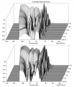
MBK said:Here is my "best" in-baffle CSD for my two woofers, 6.5" on top, 15" bottom, baffle 40x24x7", no EQ, 10 ms gate, at 10 cm measurement distance, over a thick futon on the floor. Both clearly show the "shoulder" below 1k starting around 1 ms into the CSD.
As a MLSSA old-timer, here are some hints on getting a usable CSD (your data is unfortunately not usable in terms of saying anything about the drivers).
Start by looking carefully at the time domain. The data after the first reflection is useless - one reflection alone introduces severe combing in the straight frequency response as calculated by the FFT, and the "solutions" of a very short measurement window, or 1/3 octave filtering, reduces the utility to the data to little better than the hand-drawn Fostex curves. (Always be suspicious of FR curves with fat lines - that's not how they come out of any instrument I've seen - either pen recorder or computer data.)
The shortest time window that's of much use is 6 mSec, with 8 or more preferable. The floor reflection, unfortunately, comes in around 3.5 mSec, spoiling the data. I found I had to build a pile of pillows and assorted household furnishing (couch cushions, winter clothing, duvets, etc.) about 2 feet high and 3 feet deep in order to attenuate the floor reflection by 20 dB or more. You'll see the floor reflection go down in magnitude as you keep building the pile.
If you're the curious sort, it's interesting to examine the FFT of the floor reflection by itself (by gating out the direct sound). I found that for typical wall-to-wall carpeting, the floor reflection was full-strength up to 8 kHz, where it finally started to decline in magnitude. So much for carpeting being a good wideband absorber.
Once you deal with the floor reflection, unless your living room is really huge, you'll see the ceiling or side wall reflection come in around 6~8 mSec or so. The benefit of measuring outdoors is you only have to contend with the ground reflection, which can be removed by the usual 2-foot pile of soft materials.
Once you've dealt with the floor or ground reflection, your gating interval should be set by the next reflection that arrives - be sure to exclude that reflection. The longer the uncontaminated time interval, the better the frequency resolution will be (in direct proportion) and the CSD's will "clean up" and be more usable.
For dipole, the rear wave diffracting around the baffle contaminates the measurement. Your ear and the FFT do not hear in the same way: your ear is a cross-correlator, with excellent memory of preceding (and anticipated) sounds, and can easily discriminate things that are just clutter and noise to the FFT and CSD. The FFT system has no memory, and does not build up a long-time store of the acoustic characteristics of the local environment, while your ear does all the time with no effort on your part.
In fact, if this complex and ever-shifting acoustic environment disappeared, even while you slept, you would notice immediately and go into a threat-assessment mode. You would not be relaxed, but very alert and wary. This is part of your endowment as a mammal and a human being, and cannot be turned off. But the FTT has no acoustic memory and knows nothing about its acoustic environment.
So you have to cater to its deficiencies, which is an inability to separate out different sources of sound. The diffraction coming around the edge of the baffle is just as disruptive to the FFT as the floor reflection, and will make the CSD fill with artifacts, making it unreadable.
The only solution here is a BIG baffle, made from scrap wood. Vibration isn't that important for the fairly quiet measurements you'll be making. Although I recommend scrap wood, it is still very desirable to inset the driver so the front frame is exactly flush with the face of the baffle. Small mounting errors of 1 or 2 mm can severely degrade the measurements for a tweeter, for example.
I've never tried anything as audacious as cardboard for making OB measurements - I suspect it is acoustically transparent enough to spoil the measurements. Then again, if it comes down to a too-small baffle vs a baffle extended with several feet of cardboard, yes, I'd use the cardboard. Even a bad baffle is better than no baffle.
Hope this helps. First you need clean time data, with an obvious ring-down and decay before any reflections arrive. The FFT and CSD must be derived from this "clean" time window, not contaminated with reflections.
Hi Lynn,
completely agree with your assessment. While I did take care to window out reflections bar the floor, and dampened the floor by measuring above a futon bed (i.e. futon 1 ft above the floor and speaker above that, quite "good enough" to get halfways decent simple FR without dramatic florr induced peaks), it is in my opinion the OB rear wave that contaminates it and makes it unusable.
One strange thing that I could not explain is that shifting the time domain window by just a few FFT samples (that is, tens of micorseconds) could change the CSD's look completely. I think there is also a lot of windowing artefacts in there, I suppose the fix for that is ... more experience in measuring.
Michael: yes, both dips and peaks in the FR are an expression of energy storage and both will show in the CSD. In a perfect world, a perfect EQ of peaks and dips should perfectly get rid of this 🙄
Hi
Can you show an example of that by making a screenshot of different windows in use?
Having different drivers in an OB that perform comparable under comparable measuring conditions might tell us something about the measuring technique (as Lynn outlined ) AND may also direct our attention to one thing ore two that can be learned about OB behaviour.
Therefor I was curious about the resonance that seemed to start with delay corresponding to a dip in the FR (which would be quite unusual) and asked for a slight variation in measuring setup for comparison.

Greetings
Michael
One strange thing that I could not explain is that shifting the time domain window by just a few FFT samples (that is, tens of micorseconds) could change the CSD's look completely.
Can you show an example of that by making a screenshot of different windows in use?
Having different drivers in an OB that perform comparable under comparable measuring conditions might tell us something about the measuring technique (as Lynn outlined ) AND may also direct our attention to one thing ore two that can be learned about OB behaviour.
Therefor I was curious about the resonance that seemed to start with delay corresponding to a dip in the FR (which would be quite unusual) and asked for a slight variation in measuring setup for comparison.
Greetings
Michael
Here we go, variations I did one day before, with a shorter gate and less attention to eliminating room effects.
Top and bottom are from the *identical* pulse measurement, gating length and FFT resolution are also identical. In the top graph the gating starts something like 2 FFT samples before the impulse visibly starts. In the bottom graph it starts 2 or 4 more samples (can't remember) earlier than in the top. Very small difference, hardly visible to the eye on the screen looking at the impulse resonse. Note that when I started the window precisely at the "knee" of the impule in the time domain, the FR was off - the windowing of the CSD probably adds on top of the windowing of the main impule response.
The resonance that starts with a delay at a dip, in my view is nothing but the rear wave signature. Since the FR in the CSD even at t0 already contains in this case 5 ms, it also contains part of the rear wave... just not its full decay.
Basically yes it is interesting to see how a CSD of an open baffle looks like. But as I saud above, and as Lynn has explained in detail, the CSD jumbles all sorts of time domain dependent phenomena into one graph. The ear is actually capable of keeping front and rear wave apart, under certain conditions (our sensitivity windows) so a CSD with all sorts of slow decays aand peaks and valleys translates into an open sounding, detailed speaker ... at least that's my subjective impression of it
  .
.
Top and bottom are from the *identical* pulse measurement, gating length and FFT resolution are also identical. In the top graph the gating starts something like 2 FFT samples before the impulse visibly starts. In the bottom graph it starts 2 or 4 more samples (can't remember) earlier than in the top. Very small difference, hardly visible to the eye on the screen looking at the impulse resonse. Note that when I started the window precisely at the "knee" of the impule in the time domain, the FR was off - the windowing of the CSD probably adds on top of the windowing of the main impule response.
The resonance that starts with a delay at a dip, in my view is nothing but the rear wave signature. Since the FR in the CSD even at t0 already contains in this case 5 ms, it also contains part of the rear wave... just not its full decay.
Basically yes it is interesting to see how a CSD of an open baffle looks like. But as I saud above, and as Lynn has explained in detail, the CSD jumbles all sorts of time domain dependent phenomena into one graph. The ear is actually capable of keeping front and rear wave apart, under certain conditions (our sensitivity windows) so a CSD with all sorts of slow decays aand peaks and valleys translates into an open sounding, detailed speaker
... at least that's my subjective impression of it .Attachments
Hi
No need to worry about that.
As far as I can see these two CSD's look exactly the same if you omit the first 10 slices ( T = 0 - 0.6 ms ) or so from the lower diagram (showing all the same FR) and also cut away the last 10 slices ( T = 1.86 - 2.46ms ) or so from the upper diagram.
In this example it seems that you shifted the window in the time domain by around 0.6ms and left the overall window length unchanged.
Nothing wrong here exept that you might have cut away the FR in the upper diagram by one or two slices.
Greetings
Michael
One strange thing that I could not explain is that shifting the time domain window by just a few FFT samples (that is, tens of micorseconds) could change the CSD's look completely.
No need to worry about that.
As far as I can see these two CSD's look exactly the same if you omit the first 10 slices ( T = 0 - 0.6 ms ) or so from the lower diagram (showing all the same FR) and also cut away the last 10 slices ( T = 1.86 - 2.46ms ) or so from the upper diagram.
In this example it seems that you shifted the window in the time domain by around 0.6ms and left the overall window length unchanged.
Nothing wrong here exept that you might have cut away the FR in the upper diagram by one or two slices.
Greetings
Michael
Well, the problem I see is that the cutoff is subjective: if I start too late, I get a good looking decay, if I start too early, I get a bad looking decay. Comparing the two in this example clearly shows that one did indeed start too early, and so the software produced a spurious initial plateau, and then an essentially identical decay to the second measurement.
But, unless I produce a whole series of CSD's I have no way to find out whether I chose the window correctly. Worse, even with several trials I am basically left with subjectively picking the one that looks best to me... After all, the first slices of slow or no decay could possibly be real.
The frequency dependence of the result is not making it easier. Say, I could be choosing a window where the HF had enough samples to produce a correct initial FR from which to decay. The LF however could be just short of it, with subtly altered FR and wrong decay.
To me it looks like the LF with its slow decay is likely due to artefacts, mainly, not enough samples and time slice windows cutting into what samples there are. In all my CSD's, and Paul's as well, the LF shows a broadly increasing decay time with decreasing f. A woofer should have it much easier to stop at LF than at HF. And, the problem of interpretation: I see the point now why some software expresses the decay in cycles for each f, rather than time - it makes whole lot more sense.
Hi
No, within its limitations they look exactly the same!
At least your software should have parameters to be set for the time interval of each slice and also the total number of slices.
Chose a larger T (z - axes) to plot the whole decay. You should not be limited to the 2.46 ms of your example.
Shure, if you measure only for a very short time you never can tell anything about low frequencies
Miss that too. Maybe we will have this switchable some time ?
Greetings
Michael
Well, the problem I see is that the cutoff is subjective: if I start too late, I get a good looking decay, if I start too early, I get a bad looking decay.
No, within its limitations they look exactly the same!
But, unless I produce a whole series of CSD's I have no way to find out whether I chose the window correctly.
At least your software should have parameters to be set for the time interval of each slice and also the total number of slices.
Chose a larger T (z - axes) to plot the whole decay. You should not be limited to the 2.46 ms of your example.
The LF however could be just short of it, with subtly altered FR and wrong decay.
Shure, if you measure only for a very short time you never can tell anything about low frequencies
I see the point now why some software expresses the decay in cycles for each f, rather than time - it makes whole lot more sense.
Miss that too. Maybe we will have this switchable some time ?
Greetings
Michael
I'm pretty much in 100% agreement with Zaph's measurement protocols, especially his comments on driver baffling and mounting. This is the way to do it and get clean, repeatable results.
The section on "Cost and Values" makes a lot of sense to me, and mirrors my own experiences with the same drivers he mentions.
At US$230 from E-Speakers, SoundEasy V13.0, combined with the M-Audio 192/24 PCI card, is starting to look good as a MLSSA replacement. I've already got the M-Audio card mounted in my HTPC-format PC, now it's time to order the software and learn to use it.
Hm, so I re-read Zaph's setup section - looks like he uses a 4x6 ft baffle, very well built (150 lbs!). His CSD's for woofers accordingly extend to about 200 Hz at t0 to 400-500 Hz at 3 ms, that's due to the baffle size. Trouble is for the intended woofer passband here up to 1.2k max or so that's still just the bare minimum. I'll have a go using a larger baffle and outdoors but I won't go to sophisticated constrained layer damping, just bracing.
Michael: yes I can set the parameters for the slices etc in Arta, my concern was just some kind of objective method to determine where "t0" should be.
Michael: yes I can set the parameters for the slices etc in Arta, my concern was just some kind of objective method to determine where "t0" should be.
equippment
Hi
For a good mic you might also have a closer look at the Earthworks page.
http://www.earthworksaudio.com/3.html
"http://www.earthworksaudio.com/3.html"
I own, use and love the M 30BX (battery powered) and the QTC 1 (around 45 kHz / –3dB) type.
Both are reliable and great performers not necessarily for measurement only.
Greetings
Michael
Hi
At US$230 from E-Speakers, SoundEasy V13.0, combined with the M-Audio 192/24 PCI card, is starting to look good as a MLSSA replacement. I've already got the M-Audio card mounted in my HTPC-format PC, now it's time to order the software and learn to use it.
For a good mic you might also have a closer look at the Earthworks page.
http://www.earthworksaudio.com/3.html
"http://www.earthworksaudio.com/3.html"
I own, use and love the M 30BX (battery powered) and the QTC 1 (around 45 kHz / –3dB) type.
Both are reliable and great performers not necessarily for measurement only.
Greetings
Michael
Attachments
Member
Joined 2003
You guys have been busy! I’m just catching up, so some random thoughts…
Regarding the baffle shape, I believe there are valid reasons for both symmetric and asymmetric baffles. With a symmetric baffle, diffraction effects are equal for both the left and right sides so the crossover may require more EQ for flat on-axis response. However, whatever is done in the (perhaps more challenging) crossover results in identical left and right off-axis response. With +/- diffraction impact, asymetric baffles can be less challenging for flat on-axis response (easier crossover EQ) but left and right off-axis response will be asymmetric. Does this have a significant impact on imaging? Dunno. John K and SL both seem to favor symmetric baffles, but other respected designers go asymmetric...for slightly different reasons, both seem valid choices.
A null at a tear drop edge would require symmetrical front-rear radiation…which isn’t likely considering basket interference etc. Even if driver radiation were symmetrical, a real-world driver’s acoustic center is not centered within the depth of the baffle (except for ESL etc). However, if the tear drop were reversed (with the edge near the driver) there would be minimal cavity resonance at the driver plus a large roundover at the baffle perimeter for both the front and rear wavefronts. If the distance and roundover are large enough, short wavelength wavefronts will dissipate with distance traveled along the baffle surface. Long wavelengths should cancel when they meet regardless of where they meet on the front-back path.
MJ…interesting observation regarding the feathers on an owl’s wing...they are scary quiet! An infinitely large roundover seems best, but also infinitely impractical…so we need alternatives! Are you suggesting kerf slices in line with the direction of wavefront travel (perpendicular to the sides of the baffle)?
MBK
More food for thought on compression drivers…for a passive implementation, we’re going to scrub off 10-15db of sensitivity to get flat response out of the larger format drivers. A supertweeter seems like an alternative but, in a recent post on Audio Circles, John K reminded me why I cringe every time I see a ST about a foot closer to the listener than the compression driver below it…without the proper delay, arrival time is off by multiple wavelengths! So, that is a rather loopy way of getting back to the BMS coaxial compression drivers. I hate the thought of doing two filters feeding choppy impedance curves, but coaxes would optimize both sensitivity and arrival time. I’ve only seen a few subjective comments on the BMS coaxes, but they were all positive…and I’m happy with the 4552 within it’s limits. Cost is far less than 18S, particularly considering a good ST. I like neo drivers, but I can’t see $100 per driver difference between the 4590 and the neo. Just food for thought…
Did you see the quote in one of the attachments in Lynn’s thread? “Before about 700us, the origin of a sound can be disturbed by a reflection. This error in location is a function of the relative level of the reflection. Sharp-edged rectangular speakers produce strong reflections in exactly this delay region and so are not capable of stereophonic fidelity.”
Out of curiosity, I wheeled one of the BMS 18N850s out to my concrete “launch pad” for LF CSD. Here it is at 100mm which seemed to give a fairly clean driver display. I wanted to do short range ground plane but didn’t have a safe way of holding the baffle at such a steep angle. Too expensive to stick a hole through the cone!
Anyhow, just FYI…
Hi Paul,
agree about the symmetric / asymmetric trade offs. That's something to try out I suppose, I usually prefer symmetric, question is, for a large horn / baffle, the feathering's function, besides mouth reflection dampening, would be to mimic room reflections outside the 700 us window - like a diffuser. BTW haven't seen the quote (yet) but I do remember the number from another source, one of the reasons why I made my baffles so wide (24"), to get at least close to that figure. To really reach it the baffle would have had to be 36" wide...
BMS coaxes - they got several points to go for them - they reach lower than usual 1.4" or 2" drivers (300 Hz!) and avoid the beaming issue, plus supertweeter conundrum. Though I have seen comments (Troels Gravesen?) on how in the 10k+ region time alignment is a) futile (wavelength too short, a few degree off axis listening and the alignment is off anyway) b) not necessary because we can't hear offsets in this region. Active x-o and amplification is not a problem for me, choppy impedance might however indicate other issues.
On the downside for the coaxes, BMS price is cheaper than 18S but not quite a bargain yet, it's more like +- 80 USD or so. Also, where does the money go - more parts (BMS coax) or optimized diaphragm etc (presumably 18S 1.4"). Price is usually not completely arbitrary, since we are outside of audiophile cloud cockoo land. And to actually use that fantastic 300 Hz lower limit would require an imperial sized horn.
So, what's the best compromise... really hard to tell and maybe subjective anyway. One would have to both buy and optimize two drivers before saying anything definitive. Somehow to me, so far, a 1.4" by gut feeling seems the best and simplest compromise. But. Thoughts in evolution...
I'm just in the process of gluing together a block for the first prototype horn, then we'll see how much this approach is worth to begin with...
18" CSD: looks smooth... still I think a lot of the 1ms+ data is backwave... hope I can glue some scrap panels together for a larger baffle and then I retry my woofers.
Member
Joined 2003
My understanding is the erratic impedance curve for compression drivers is usually caused by the horn/WG. The fine print on the marketing sheets says the 18Sound impedance curve is free air, while BMS impedance is measured on a horn. It could be that a "perfect" WG would provide smooth impedance curves.
Sounds plausible.
BTW edit, my 24" baffle does indeed place the first edge reflection outside the 700 us window, the minimum baffle width for this is 18" not 36". Phew. I started wondering why I chose my dimensions as I did.
BTW edit, my 24" baffle does indeed place the first edge reflection outside the 700 us window, the minimum baffle width for this is 18" not 36". Phew. I started wondering why I chose my dimensions as I did.
Nice CSD Paul! Clearly the larger driver/high gauss/linear suspension.. maintains a more linear short-term decay - and is particularly impressive below 200 Hz. 😎
Note that the driver exhibits the same discontinuities that MBK was concerned with.. this time however those discontinuities go further down in freq.. (..MBK - think about that a little further 😉 )
About the symmetrical "tear drop" shape:
Remember the dipole "null" is largely dependent on the path length and the directivity of the driver. Here modeling with the Edge is quite useful. A 16" baffle nets us a maximal null right around 100 Hz, and a -3db point just below 200 Hz (..driver dependent though). The compound (and largely) canceling turbulence at these freq.s will break-up diffraction effects from higher freq.s reflecting from the baffle near this edge. The net result is something near a "disappearing" edge that higher freq.s can't react to, while still maintaining a fairly shallow mounting depth for the driver.
Functionally the overall shape of the baffle wouldn't look dramatically different from the Sonus Faber Stradavari (..though of course the side edges would be significantly tapered by comparison).
About BMS Coaxials:
I don't think that the basic BMS design will give you quite that non-compressed ultra-fi sound when comparing the midrange driver portion of the BMS vs. the Radian 2" in the 800-6400 Hz range. Of course I could be wrong - so the usual caveats apply.
Additionally - the ONLY thing that the BMS design will net you in a low "compression" horn that is practical in size, is a better decay signature near its resonance, and an actually lower resonance. That in itself may or may not be significant - depending on the operating passband for the driver (..including the filter).
Now the coaxial super tweeter..
Again - in a low "compression" horn, the super tweeter will likely be unloaded for a good bit of its passband. Because of this, linear and non-linear distortion goes up significantly. While the sound will still retain that electrostatic-like "speed", the decay will however be compromised - and in fact sound more like an actual electrostat (..as opposed to a ribbon's sound). Also, directivity will still be an issue (i.e. it will "beam").
You can *mostly* get around these problems with a well designed more "compressed" format horn with a deeper throat. Unsurprisingly, such a design will also allow the midrange to extend lower in freq. for a given size.
Considering the above - the BMS coaxial units are better utilized with a horn similar to Bert's Orphean (..though perhaps with greater "round over" like the Azurahorns).
I think then the choice of a BMS coaxial vs. the Radian 2" while utilizing appropriate horn designs comes down to a matter of listener "taste". If you want greater directivity and a lower freq. response that will sound more "detailed" - then go with the BMS coaxial. If you want wider dispersion and a more "laid-back" and "natural" sound with still excellent detail then go with the Radian/large format horn/dipole driver. Of the two - I would caution the user/listener about the former BMS version.. some people (myself included), may like the sound initially, but ultimately be unhappy with it because of the increased "compression" and the resulting decreased directivity.
Paul W said:Are you suggesting kerf slices in line with the direction of wavefront travel (perpendicular to the sides of the baffle)?
That's how it is done on the Iwata horns and tunnels.
Jack Bouska talks about towels around the edges of horns to ease the impedance transition. Similar idea. Should apply to the edges of a baffle, though perhaps with less effect than on a horn.
ScottG said:Here modeling with the Edge is quite useful. A 16" baffle nets us a maximal null right around 100 Hz, and a -3db point just below 200 Hz (..driver dependent though).
Note.. that was with about a 40 inch high baffle and driver placement relatively near the floor. (..*perhaps* similar to what would occur in such a design). Of course IF its centered on a 16" by 16" baffle - then the path length vs freq. null more closely matches what you would expect of the null considering the freq. (.i.e it moves up in freq.). But its unlikely that the driver would be used that way when considering the overall design (especially if used with a super tweeter).
Of course if you don't use a super tweeter (or if its coaxial), then you could always use a midrange "filler" above the horn/compression driver. There you could come close to maximizing your cancellation and at least "shoot" for something approaching constant directivity down lower in freq..
Anyway.. the "disappearing" edge concept still applies.. It does however become increasingly moot when you have less and less baffle to work with.
Member
Joined 2003
Hey Scott,
panomaniac,
Do you have a link to the kerfed Iwata horns? A quick Google didn't turn up any kerfs.
Assuming turbulence exists in some regions, the bass would have to be in incredibly fortuitous sync with a singers voice to cancel HF diffraction signals resulting from her song. I agree the baffle could look very, very good, but don't think it will function as envisioned...perhaps in isolated instances, but not across the musical spectrum. But, I've been wrong before and will be a zillion times again😉The compound (and largely) canceling turbulence at these freq.s will break-up diffraction effects from higher freq.s reflecting from the baffle near this edge.
Radian is not on radar without reasonable data. It is very unusual that an Engineering department doesn't have basic test data on file. Heck, SEAS publishes much more useful information for $30 tweeters! For now, it's between 18S and BMS.I don't think that the basic BMS design will give you quite that non-compressed ultra-fi sound when comparing the midrange driver portion of the BMS vs. the Radian 2" in the 800-6400 Hz range. Of course I could be wrong - so the usual caveats apply.
The BMS also allows placing the ST acoustic center near the correct distance from the listener. ST combined with a 2" exit will either be wavelengths too close to the listener, or, fire toward the back of a larger mid/tweet horn.Additionally - the ONLY thing that the BMS design will net you in a low "compression" horn that is practical in size, is a better decay signature near its resonance,
This agrees with the BMS distortion plots. However, the only 2" exit distortion plots I have also show higher relative distortion at higher frequencies...apparently no difference.Again - in a low "compression" horn, the super tweeter will likely be unloaded for a good bit of its passband.
Got me there...why will a 2" exit have wider dispersion than a 2"/1" coax?If you want wider dispersion ... then go with the Radian/large format horn/dipole driver.
panomaniac,
Do you have a link to the kerfed Iwata horns? A quick Google didn't turn up any kerfs.
Latest CSD is looking good, you can actually see the driver taking off at 1 kHz. 18Sound as usual comes through. Looking forward to auditioning these drivers, they look like serious players, and a welcome departure from the low-efficiency world of Vifa, Seas, and Scan-Speak.
Regarding Edge, which I've playing with the past week, it doesn't show the floor reflection. This is a big deal when the baffle extends down to the floor, as my design will. So far, I've simulated the floor by simply creating a mirror-image of the baffle, complete with drivers, underneath the "real" baffle. Since the floor is close to 100% reflection, this seems like a valid approximation.
Where it gets a little weirder is when the baffle slopes back a few degrees, something I'm thinking of doing so the bass and widerange drivers have the same arrival times for the listener. Modeling in this in Edge can be done - to the first approximation - by moving the simulated "mike" downwards (to the center of the baffle), but the images in the mirrored floor reflection are altered. The mirror-image drivers move further downward to simulate the increased distance from the listener, but the mirror baffle doesn't. Weird.
Interesting comments about the BMS coax. For a moment I thought you were talking about the BMS coaxial cone/horns, which have pretty scary-looking curves. The BMS coaxial CD, by contrast, looks fairly easy to use, and based on the published FR curves, it doesn't even look necessary to lowpass-filter the midrange CD. A carefully shaped 3rd or 4th-order HP for the supertweeter looks like it would slide right into the intended FR curve.
One thing that's sure to be different between the 18Sound, BMS, and Radian is the choice of diaphragm material. Measurements don't really disclose just how different these sound - and a horn, at best, will simply magnify the characteristic sound of the material. The BMS is a flexible plastic ring radiator, the 18Sound either plastic or Titanium, and the Radian is aluminum with a plastic surround. All different sounding, no matter what the curves say.
(I did have Mike at Radian e-mail me some data from their in-house comparative tests, and in the critical 10-20 kHz region, the Radian 850-PB is quite a bit smoother than the JBL Professional 2" driver, and comparable, just a little different, than the 2" TAD beryllium driver. Distortion measurements have a similar ranking. No, I don't know why they don't publish more comprehensive technical information on their website.)
The one good thing about supertweeters is that deep notches in the FR at 8 kHz or above are not readily audible, unlike around 3 kHz, where they are easily heard a "phasey" artifacts. It's annoying to measure ST crossovers because the mid and ST are typically several wavelengths apart, so moving the mike makes all sorts of ripples in the space of a few inches. But you'll find with pink-noise drive, the nulls - that are so visible on a spectrum analyzer - are surprisingly difficult to hear, even if you're moving around and listening directly for them.
Part of this is because this HF region is the domain of the outer ear, the pinna, and recordings don't have any height information on the disc - except by accident, as a result of spaced-microphone random phase relations.
- Status
- Not open for further replies.
- Home
- Loudspeakers
- Multi-Way
- Large midrange for OB??? Scott G ?