LT317/337 is even better and a cheap trouble free 100% pin compatible upgrade if you ever get around to wanting to do such a thing
oh and your hutch...DO WANT!!
Thanks 🙂
My power supply is not audiophile grade, so I'll make due with the LM317 (these are cheapest - I have them already
 )
)Love the parts hutch John. Sure puts my pile of plastic bins to shame.
Thank you! 🙂
make two in flat pack form and surface ship them to Scottish Borders. NOW!!!!
Hey, if you can pay the shipping...🙂
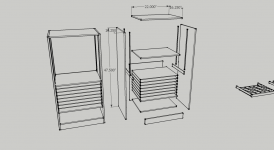
It isn't difficult to DIY - if you want it, I can give you the Sketchup drawing that has all of the parts and exact dimensions. Takes all the guesswork out of it. Just measure, cut and assemble...and assemble...and assemble...
yeah just thought i'd mention it, for true audiophile grade there would be something else, the lt317/337 are only a few dollars each, but I get wanting to use what you already have, especially when having to go to such lengths to store everything 😉 seriously, I would love one of those things, the sketchup file would be awesome, but I reckon you could make good money out of selling them to us here if you could find somewhere that would assemble them cheaply and ship flatpack as Andrew said. probably not worth doing it yourself as would take too long to make it viable, would have to sell for too much, but maybe somewhere in asia?
but i'll take those files if you are offering, that would be awesome!!
reckon I could find someone here to do it for not too much, would be worth a few hundred to me
but i'll take those files if you are offering, that would be awesome!!
reckon I could find someone here to do it for not too much, would be worth a few hundred to me
but i'll take those files if you are offering, that would be awesome!!
Here it is:
View attachment Parts and Gear Hutch.txt
Just change the .txt extension to .skp
thankyou very much, I just realized I used the word awesome!! 2 times in one post hehe, it really is though, so thanks
After the long work week, I did manage to get some things done today. I moved the hutch (hutch is actually the wrong description. Originally it was going to be a shelf unit that sat on top of my bigger drawer unit (aka a 'hutch') but that got changed to the free standing model it is now.) down stairs to my lab and put the scope, FG and the still unfinished power supply in it:

Looks nice. No parts in the drawers yet - I need to get other things organized first. My plan is to put 1/4 watt resistors, small value film, mica and ceramic caps and small signal transistors. As all of the bins are small, small parts make the most sense.
I stuck all of the switches, knobs and binding posts in the power supply, just to see how everything is spaced and it all looks good:

I did the fix on the LM317 on the regulator boards:

and tried them. They work just the same as they did when they were wrong - interesting! I can't understand that, it must be my incredible good luck.
Next, I will assemble half of the digital pot board and try it. This I am nervous about, especially my first crack at surface mounting a component. Hopefully, the circuit works as planned.

Looks nice. No parts in the drawers yet - I need to get other things organized first. My plan is to put 1/4 watt resistors, small value film, mica and ceramic caps and small signal transistors. As all of the bins are small, small parts make the most sense.
I stuck all of the switches, knobs and binding posts in the power supply, just to see how everything is spaced and it all looks good:

I did the fix on the LM317 on the regulator boards:

and tried them. They work just the same as they did when they were wrong - interesting! I can't understand that, it must be my incredible good luck.
Next, I will assemble half of the digital pot board and try it. This I am nervous about, especially my first crack at surface mounting a component. Hopefully, the circuit works as planned.
Hopefully, the circuit works as planned.
It does! 🙂
I only did one pot to try it out:
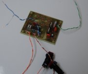
A little slow ticking up and down so maybe I'll change the RC constant on the oscillator to speed things up a bit.
I have one other concern that I didn't consider before: will 100 taps be enough resolution? I guess the best way to find out is to wire it into the supply regulator and try it. There are digital pots with a higher number of taps but none can handle the voltage that the X9319 can.
Another thing that I would like to do differently is the up/down switching arrangement. Right now I have a mom switch for each but what I would rather have is a mom-off-mom toggle switch. 'Up' is voltage up, 'down' is voltage down.
I fretted over the surface mount X9319 for nothing. It was relatively easy to solder:
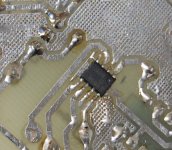
And no holes to drill! 😎
A guy at school likes to brag about his soldering skills. Last week he showed me a board he had made where he had hand-soldered 0201 size passive components. They are smaller than just the leads of a SOIC at 0.3 x 0.6 mm 😱
I haven't soldered much surface mount but the SOIC, 1206 and 0805 sizes I've tried are pretty easy. A great advantage that you do not have to drill any holes. 😉
I haven't soldered much surface mount but the SOIC, 1206 and 0805 sizes I've tried are pretty easy. A great advantage that you do not have to drill any holes. 😉
They are smaller than just the leads of a SOIC at 0.3 x 0.6 mm 😱
That would be TOO small for me. Not to mention that I'm pushing the envelope as far as laser transfer homemade boards go with this size of SMT.
Still, I expect I'll see a lot more of this in my future.
The digital pot connected to the regulator board:
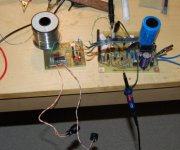
Works very well. Each 'tick' of the pot increments or decrements the output voltage by 0.4VDC. This is not bad at all. Output voltage from the regulator goes from 0.18VDC to ~36VDC.
I also think the oscillator timing is fine at ~3 'ticks' per second, so I'll leave the RC values as is.
I need to stuff the other side of the board and test that pot. Once I have verified it's working properly, I can install the regulators back in the case and mount the pots board and switches.
The current limit adjust is just a regular 1K pot that will have a knob. These can be mounted as well.
It's coming together.
very cool, yeah soic8 is nothing to solder, easier than through hole, well at least quicker, with nice flux is possible to solder soic8 in 2 swipes, 1 for each set of 4 legs
very cool, yeah soic8 is nothing to solder, easier than through hole, well at least quicker, with nice flux is possible to solder soic8 in 2 swipes, 1 for each set of 4 legs
😱 No! Not for those of us that have less than perfect eyesight. It wasn't hard but it wasn't easier than through hole. I'm with you on quicker though, no leads to cut off.
I think I've screwed up. The digital voltage control pots should have been separated, one to each supply. I combined them on one board, running on one power supply. This would effectively connect the '0 volt' on both supplies and they would no longer be isolated.
I guess I'll have to either do some surgery on the board to split the ground and rail supply or make a new board and try to salvage those parts. Sometimes I do the stupidest things...
Anyway, lots of stuff done today and since a pic is like 1000 words, here are 2K:
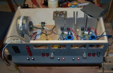

If anyone thinks it is trivial to build one of these, they really need to give it a try. Much time spent on all this wiring.
Save those defunct FDD cables! they make great low current ribbon cable.
looking good mate!! sounds like there is a razor blade in your future for separating the grounds. I actually do find them easier, but have the benefit of quite a lot of SMD experience and eyes and nerves of a 36yr old. not that PTH is harder really, probably about on par, but when you factor in time its for me easier. no way is this an easy build you are doing, really quite impressed, particularly casework and grounding would be tricky for keeping noise at bay.
looking good mate!! sounds like there is a razor blade in your future for separating the grounds.
I cut through the ground plane on the pots board and removed the +rail jumper to that side. I'll air wire another R/zener/LM7805 to supply that half of the board.
When I'm finished this project, I'll probably make a whole new board for the pots but for now, I just want to get it done and tested.
For the current adjust, I needed a 500R - 1K pot and the recycled knobs I had are for a knurled shaft. Not many options at Digikey for this combination. The pots I ordered are board mount, with no collar nut for panel mounting. How to mount to the panel?
The solution I came up with is one of the many things that are a challenge in a project like this and really adds to the time it takes to build:
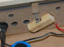
Simple but effective, these blocks were notched for the pot and glued in place. I then screwed thru the face into the blocks to add more support (just pushing the knob onto the shaft may have broken the blocks loose). The down side is that these pots are now trapped, making them harder to replace. This should be a problem, unless somthing happens to one of them.
Last edited:
I cut through the ground plane on the pots board and removed the +rail jumper to that side. I'll air wire another R/zener/LM7805 to supply that half of the board.
Successfully done:
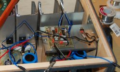
The pots work fine and they are completely isolated from each other. I'll leave it like this for now, until I make another Digikey order. I'll make a new board at that time, save the X9319's and trash the NAND ICs (too hard to remove and only cost 75 cents each).
The supply in operation:
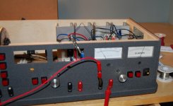
That's 15VDC @ 1.8A. The ammeter still needs a slight adjustment and I need to re-scale and re-shunt the other one.
I had the current limit adjust pots wired backwards and fixed that. Current adjust seems to be very accurate and I have full scale use of the pot.
I get so many ideas from looking through your threads (more action 😀). You are a valuable resource , excellent work ... especially with the layout/ manufacturing.
OS
OS
Thanks Pete 🙂
Hopefully a few readers will take inspiration from what we do and build something. For a DIY site, there's a whole lotta talk going on.
Action speaks louder than words
I fixed up the other ammeter and installed it:

Having the voltmeters scale to 75VDC is a pain but I can live with it. The ammeters are now calibrated to a 3A scale and that is perfect for this supply.
A look at the back of the meters shows the 100 ohm trimpots I installed to adjust the ammeters:
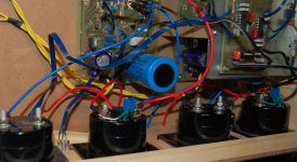
The location I chose for the digital pots board mounting blocks access to the second supply. I can't reach the trimpots that adjust the current limit threshold and the reference voltage. I guess I'll have to find a different place for it. Even with a large case like this, space is tight.
One thing I was going to do on redesign of the digital pots board was to add a battery backup to maintain the levels when the unit is shut off or a way to set the CS and INC pins on the X9319 to logic high before Vcc is applied (this recalls the level from memory). Now, I'm not sure if that is the best approach. As it is now, on power up the pots are at level "0" and this means no output voltage at the binding posts. This may be the best way to have it, no accidental shorts and in reality you will need a new voltage every time the unit is turned on anyway.
I did some load testing and everything looks good. I can adjust the current limit right down to 0 if I want to but I set it for 10mA minimum.
I also did a brief load test with both supplies in series and found that on reaching the max current (~2.5A) only one supply starts to limit and not the other, making the voltages asymmetrical. I don't know if there is an easy fix for this or if it is even worth worrying about. One possibility it the addition of a trimpot to equalize current sense between channels - I feel it is the tolerance difference of the resistors in the current sense loop that causes the mismatch.
Next test is a parallel load test.
Hopefully a few readers will take inspiration from what we do and build something. For a DIY site, there's a whole lotta talk going on.
Action speaks louder than words

I fixed up the other ammeter and installed it:

Having the voltmeters scale to 75VDC is a pain but I can live with it. The ammeters are now calibrated to a 3A scale and that is perfect for this supply.
A look at the back of the meters shows the 100 ohm trimpots I installed to adjust the ammeters:

The location I chose for the digital pots board mounting blocks access to the second supply. I can't reach the trimpots that adjust the current limit threshold and the reference voltage. I guess I'll have to find a different place for it. Even with a large case like this, space is tight.
One thing I was going to do on redesign of the digital pots board was to add a battery backup to maintain the levels when the unit is shut off or a way to set the CS and INC pins on the X9319 to logic high before Vcc is applied (this recalls the level from memory). Now, I'm not sure if that is the best approach. As it is now, on power up the pots are at level "0" and this means no output voltage at the binding posts. This may be the best way to have it, no accidental shorts and in reality you will need a new voltage every time the unit is turned on anyway.
I did some load testing and everything looks good. I can adjust the current limit right down to 0 if I want to but I set it for 10mA minimum.
I also did a brief load test with both supplies in series and found that on reaching the max current (~2.5A) only one supply starts to limit and not the other, making the voltages asymmetrical. I don't know if there is an easy fix for this or if it is even worth worrying about. One possibility it the addition of a trimpot to equalize current sense between channels - I feel it is the tolerance difference of the resistors in the current sense loop that causes the mismatch.
Next test is a parallel load test.
Last edited:
Onward! 
I'm satisfied with the basic supply function (voltage regulation is VERY good, current limit is much better than I expected) and I have much of that part done - meters installed and connected, switches and knobs done and done. I moved the pots board to the sidewall and got rid of the hovering metal platform. It fits beautifully there and I don't know why I didn't put it there in the first place.
Next, the dummy loads:
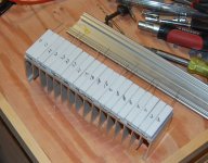
20 cement resistors, 200 watts total. I had a heatsink from a scrapped receiver that fits like a glove 🙂
The division of loads is - 32R, 16R, 8R, 4R, 2R. Power handling is 40@32R, 80@16R, 120@8R, 160@4R, and 200@2R.
Sound good?
This is connected to the other pair of binding posts and is selected with the 4 switches above them. A rather ingenious method, if I do say so.
😀

I'm satisfied with the basic supply function (voltage regulation is VERY good, current limit is much better than I expected) and I have much of that part done - meters installed and connected, switches and knobs done and done. I moved the pots board to the sidewall and got rid of the hovering metal platform. It fits beautifully there and I don't know why I didn't put it there in the first place.
Next, the dummy loads:

20 cement resistors, 200 watts total. I had a heatsink from a scrapped receiver that fits like a glove 🙂
The division of loads is - 32R, 16R, 8R, 4R, 2R. Power handling is 40@32R, 80@16R, 120@8R, 160@4R, and 200@2R.
Sound good?
This is connected to the other pair of binding posts and is selected with the 4 switches above them. A rather ingenious method, if I do say so.
😀
....rather ingenious method, if I do say so.
😀
Yeah, if it fit:
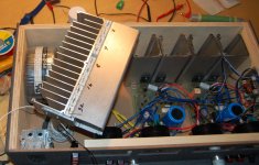
which it doesn't 🙁 I'll need to move things around and possibly chop a hole in the back panel. I can then cover that hole with a piece of sheet metal.
As for parallel operation, I tried and then it occurred to me I need current sharing resistors for that to work properly. That might be the fix for series operation as well and I'll try that out later.
Last edited:
I got it to fit:
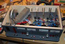
by cutting the lower aluminum rail down a bit. Someone is reading this, I know it...and in case that someone is curious, these aluminum rails are off cuts from Von Duprin panic sets:
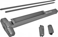
Waste not!
I wired it in to the switches and binding posts and it works just as planned.
I'm very close to the end of this project and I must say that it has exceeded my expectations.
It certainly kicks the a$$ outa my old supply. 🙂

by cutting the lower aluminum rail down a bit. Someone is reading this, I know it...and in case that someone is curious, these aluminum rails are off cuts from Von Duprin panic sets:

Waste not!
I wired it in to the switches and binding posts and it works just as planned.
I'm very close to the end of this project and I must say that it has exceeded my expectations.
It certainly kicks the a$$ outa my old supply. 🙂
Doing some testing, stuff I really should have done before making it hard to get at. 🙁
Starting with some basics that I completely gapped on, like bypass caps...
I powered up the supplies and connected my scope. Nice to quantify the magnitude of any ripple or noise coming through. Everything shown is at 15VDC output. Load is 8Ω for a current draw~1.8A.
First, no load:
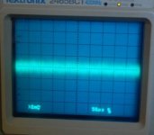
What? Doesn't look very clean.
Second, with load:
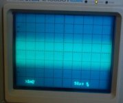
Wow! Terrible, even though the scope is at 2mV/div and the probe is 1x. Something must be amiss.
It looks like HF krap so I then realize that I DON'T have bypass caps on either the main or the doubler. How did I miss that?
Installed those caps and how it looks now:
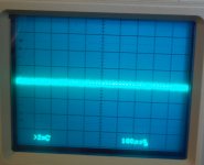
That was no load. Pretty clean.
With the load:
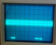
Much better than before but still not great. I fiddle with the current limit adjust knob, turn it up and down and on turning it down to where it just starts to limit the output current I see this on my scope:
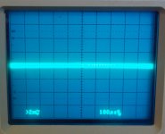
That is 15VDC @1.8A.
So, it looks like maybe the current limit transistor is doing something funky when it isn't sinking current. Possible oscillation? Changing the time base on pic #4 shows what faintly looks like oscillation.
Suggestions? Comments welcome.
Starting with some basics that I completely gapped on, like bypass caps...
I powered up the supplies and connected my scope. Nice to quantify the magnitude of any ripple or noise coming through. Everything shown is at 15VDC output. Load is 8Ω for a current draw~1.8A.
First, no load:

What? Doesn't look very clean.
Second, with load:

Wow! Terrible, even though the scope is at 2mV/div and the probe is 1x. Something must be amiss.
It looks like HF krap so I then realize that I DON'T have bypass caps on either the main or the doubler. How did I miss that?
Installed those caps and how it looks now:

That was no load. Pretty clean.
With the load:

Much better than before but still not great. I fiddle with the current limit adjust knob, turn it up and down and on turning it down to where it just starts to limit the output current I see this on my scope:

That is 15VDC @1.8A.
So, it looks like maybe the current limit transistor is doing something funky when it isn't sinking current. Possible oscillation? Changing the time base on pic #4 shows what faintly looks like oscillation.
Suggestions? Comments welcome.
Changing the time base on pic #4 shows what faintly looks like oscillation.
None too faint:

That is at 2uS and is the 15VDC into load without limiting.
This is the same time base, the current limiter just starting to limit:
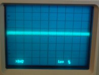
This is the same as above but at 2mS:
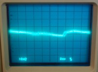
THAT looks like mains ripple and if it is, I'm QUITE pleased with that outcome. Ripple as low as that when drawing 2A @ 15VDC =

Now, I'm back to the drawing board to try and come up with a reason and solution for this obvious oscillation. Possibly increase C7 from 470pF to 680p?
- Status
- Not open for further replies.
- Home
- Amplifiers
- Power Supplies
- Lab Power Supply Design / Build