Spent some time last night re-drawing the scale for the ammeters. This is a very frustrating job and took quite a while. The results are rough but acceptable:
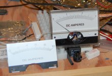
These meters had an internal 10A shunt and the scale went to 10A. This is too high for my supply and I decided to resize it. I removed the internal shunt and installed an external one (short piece of steel wire) with a 100 ohm trimpot in parallel with it. The wiper of the trimpot feeds one lead of the meter coil, giving me enough adjustment. These will now be 3A meters and I just finished calibrating the first one.

These meters had an internal 10A shunt and the scale went to 10A. This is too high for my supply and I decided to resize it. I removed the internal shunt and installed an external one (short piece of steel wire) with a 100 ohm trimpot in parallel with it. The wiper of the trimpot feeds one lead of the meter coil, giving me enough adjustment. These will now be 3A meters and I just finished calibrating the first one.
Thanks! No plans to light them up. Should be easy enough to see on their own.
Doing some planning on the enclosure, trying to make the unit ergonomic. One of the problems with my old supply (shown in post #1) is the binding posts location. It is easy enough to attach a banana but to clamp a bare wire is difficult. In this new one, I want the posts easily accessible and to that end, I will mount them on a sloped "cow catcher" on the bottom of the front panel:
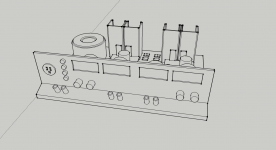
Gotta love Sketch up 🙂
The meters run across the top with the voltage and current control knob beneath. On the left is the dummy load posts and selector switches. Next to that is the current limited (via a light bulb) receptacle.
From the back:
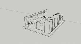
Overall size is approximately 20" wide, 5" high and 12" deep. The first step is to build the front panel and physically lay everything out to see how big the case actually needs to be.
The majority of the case will be made from 1/4" hardboard. Some solid pine and some 1/2" BB ply as well.
Doing some planning on the enclosure, trying to make the unit ergonomic. One of the problems with my old supply (shown in post #1) is the binding posts location. It is easy enough to attach a banana but to clamp a bare wire is difficult. In this new one, I want the posts easily accessible and to that end, I will mount them on a sloped "cow catcher" on the bottom of the front panel:

Gotta love Sketch up 🙂
The meters run across the top with the voltage and current control knob beneath. On the left is the dummy load posts and selector switches. Next to that is the current limited (via a light bulb) receptacle.
From the back:

Overall size is approximately 20" wide, 5" high and 12" deep. The first step is to build the front panel and physically lay everything out to see how big the case actually needs to be.
The majority of the case will be made from 1/4" hardboard. Some solid pine and some 1/2" BB ply as well.
The mock-up:
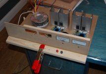
Not far off the Sketchup model. Looks like everything will fit ok.
I stuck a pair of garbage binding posts in there for illustration only.
There are some things I need to finish this:
- the pots for voltage and current control. For these I'll just use single turn pots. Knobs I already have.
- all the gear for the light bulb limiter. Trip to the hardware store for that.
- reasonable binding posts.
- switches for the dummy load selector.
Looks like a Digikey order is in order but for now, I should easily get the case done tomorrow, maybe even a coat of paint too.
good work, so combo posts then? nice idea on the 'cow catcher tm' I would normally recommend posts from my mates at eichmann just up the road for audio purposes, but probably overkill here, although the minimal amount of metal in the signal path would be a good thing all the same, too pricey though for here.
yeah sketchup works a treat, wish I had some woodworking skills, I have to pay dearly for anything I ever want made, at least I can do the cad or solidworks stuff, but I have nothing by way of tooling really, well not past a drillpress and dremel. i'm all thumbs when it comes to wood though.
so single turn pots are enough for fine adjustment you think? I would personally go for more as single turn at 5-10% tolerance isnt going to give you very precise adjustment IMO.
all the same its looking good, I have been toying with the idea of a DIY lab supply too considering the amount of quality spare supplies sitting around here unused.
Thanks again.
I actually have 2 pairs of Eichmann Cable Pods but I think I'll save those for something else. 🙂
Maybe digital pots for the voltage control is the way to go. 100 taps for fine adjustment plus the ability to link and unlink each channels adjustment (voltage would go up or down on both together when linked). A suitable candidate would be Intersil X9319. It can be manually configured easily and will handle the voltage (<10VDC) from the LM317.
Instead of a knob, 2 momentary switches to control the voltage.
The more I think about the digital pot method, the more I like it. It is also an opportunity to mess around with one - a new experience.
The circuit I'll use:
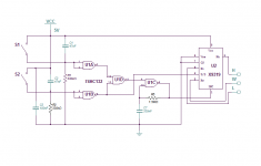
Simple enough and fairly cheap. The X9319 is less than $5 and the NAND Schmitt trigger is 75 cents. Economical enough.
Some progress has been made on the case. It is nearly done except the lid. Heatsinks have been drilled and attached and I have purchased the needed hardware for the lightbulb limiter.
Some more pics soon.
The circuit I'll use:

Simple enough and fairly cheap. The X9319 is less than $5 and the NAND Schmitt trigger is 75 cents. Economical enough.
Some progress has been made on the case. It is nearly done except the lid. Heatsinks have been drilled and attached and I have purchased the needed hardware for the lightbulb limiter.
Some more pics soon.
A couple more pics to share:
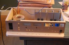
Front panel is nearly complete. All of the holes are drilled for the switches, pots. The receptacle will be split - the bottom will be straight fused (5A fuse) mains outlet and the top will be current limited through the light bulb.
By drilling holes for the up/down momentary switches, I've commited to the digital pot scheme. I hope it works.
The light socket:
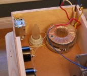
I can start on the internal wiring now. The front panel on/off switch control the transformer, leaving the receptacle live.

Front panel is nearly complete. All of the holes are drilled for the switches, pots. The receptacle will be split - the bottom will be straight fused (5A fuse) mains outlet and the top will be current limited through the light bulb.
By drilling holes for the up/down momentary switches, I've commited to the digital pot scheme. I hope it works.
The light socket:

I can start on the internal wiring now. The front panel on/off switch control the transformer, leaving the receptacle live.
Ok, when was the last time you were running something that required 2A @ 5VDC? I never have and most likely never will..
My wireless access point draws 2.5A at 5V DC and has so far destroyed the original and a replacement PSU. Loft conditions do not help for sure (very hot in summer). Has been running last two years on a custom made PSU I built explicitly for that WAP. It is like a half-brick in size.
I remember we discussed this once, I also have a laser printer at home and have tried once to "iron" a print out onto the PCB but without any success. Since it seems you are manufacturing PCBs at will, could you please create a step by step guide? 🙂
The key to ironing laser printing onto a PCB is to use the correct paper - you need a cheap single sided coated presentation or photo paper - I use Tesco value photo paper @ £1.97 for 20 A4 sheets - Print on the coated side, iron on the plain side -Then soak it off, because its cheap and cheerfull and unsized, the base paper falls apart leaving a thin layer of coating/latex which is easily removed with a plastic kitchen scourer(don't go mad with it) - I've found it far more reliable that the expensive transfer sheets that you can buy
Regards
Richard
Regards
Richard
Last edited:
My wireless access point draws 2.5A at 5V DC .
Sounds like a job for the LM323 - 3A, 5V regulator. I have 1, the steel version that I got for nothing (Digikey retail is ~$35.00!) that I haven't found a use for yet.
My supply, as it is now with 2 pass transistors wouldn't have a problem with that load. Of couse, for long term operation (as opposed to short term testing), a dedicated supply at the required power would be best.
could you please create a step by step guide? 🙂
Mostly everything I know I learned from Tom Gootee's excellent tutorial HERE. I have little that I can add regarding the printing and etching process, except to reinterate how crucial it is that the board be VERY clean.
I do have a trick for lining up the top and bottom layer to iron them onto the copper clad board. jandr49's comment above about the plastic kitchen scubby is on the money - exactly what I use.
Not a lot done over the last 2 days. I'm waiting to pull the trigger on a Dickey order, trying to think of things I'll need for some upcoming projects. No sense ordering twice (or thrice!).
Finished the internal wiring in the case. I mounted the toroid on the side, rather than the bottom.This gives a bit more free space for the dummy load setup. I still need to figure out what I'll use for the resistors (nichrome or cement resistors)
The case needs side panels and a top panel that I haven't made yet. I also want to get the whole thing painted before final assembly.
Nice spell checker flub above - Dickey instead of Digikey. 😛
I looked at the nichrome:
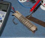
I measured it and have enough to do the initial 32 ohms (attached between the binding posts) and the rest will be cement resistors:
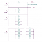
Easy enough, just need to account for the heat produced. Should be very handy in practice.
I looked at the nichrome:

I measured it and have enough to do the initial 32 ohms (attached between the binding posts) and the rest will be cement resistors:

Easy enough, just need to account for the heat produced. Should be very handy in practice.
A smidge more progress. Case is ~finished and I gave it a coating of textured paint (in a spray can):
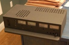
Not a great pic but the paint does make it look neat and tidy.
A look at the inside:
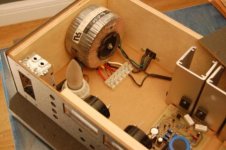
Wiring to the light bulb limiter and receptacle is done (except an inline fuse that is on order) and the transformer is wired.
Now that the case is painted, I can install the supplies and wire those to the transformer.
I have changed my mind on the dummy load. I will use cement resistors only and keep the nichrome for something else. It will take a gaggle of 10 watt resistors to make up the power and impedances I want, all clamped to a suitable heatsink.
I need a clear plastic rod, about a 1/2" in diameter to channel the light from the bulb limiter to the front panel. Maybe a hot melt glue stick would be ok.

Not a great pic but the paint does make it look neat and tidy.
A look at the inside:

Wiring to the light bulb limiter and receptacle is done (except an inline fuse that is on order) and the transformer is wired.
Now that the case is painted, I can install the supplies and wire those to the transformer.
I have changed my mind on the dummy load. I will use cement resistors only and keep the nichrome for something else. It will take a gaggle of 10 watt resistors to make up the power and impedances I want, all clamped to a suitable heatsink.
I need a clear plastic rod, about a 1/2" in diameter to channel the light from the bulb limiter to the front panel. Maybe a hot melt glue stick would be ok.
Last edited:
My wireless access point draws 2.5A at 5V DC and has so far destroyed the original and a replacement PSU. Loft conditions do not help for sure (very hot in summer). Has been running last two years on a custom made PSU I built explicitly for that WAP. It is like a half-brick in size.
Also, a lot of powered USB hubs will use a 5V supply. Quality ones will alot 500mA to 1A per port. I have several 6 ports that have 3.5A supplies.
Sounds like a job for the LM323 - 3A, 5V regulator. I have 1, the steel version that I got for nothing (Digikey retail is ~$35.00!) that I haven't found a use for yet.
My supply, as it is now with 2 pass transistors wouldn't have a problem with that load. Of couse, for long term operation (as opposed to short term testing), a dedicated supply at the required power would be best.
.
the point that was being made by Andrew was that at 5V output the pass transistor will have to drop maybe 27 or more volts across collector and emitter, and at 5 Amps this would be 135 Watts, at 3 Amps it will be 81 Watts. That is a lot of heat to dissipate. The way I understand it even witha sizeable heatsink, eg http://uk.farnell.com/abl-heatsinks/345ab1000b/heat-sink-1-c-w/dp/150016 (this brick is 1C/W), you'd be looking at boiling egg temperatures. Certainly I have used similar on my LM3886 amps and they get very hot without a fan blowing straight at them.
Thanks for the guide, I will read it / print it. I just found it very hard I remember to keep the paper perfectly still on the pcb while pressing with iron and also not all the traces got transferred, you'd peel it off to find that it was not a clean job. I will try the Tesco paper as someone else has recommended here.
Last edited:
the point that was being made by Andrew was that at V output the pass transistor will have to drop maybe 27 or more volts across collector and emitter, and at 5 Amps this would be 135 Watts, at 3 Amps it will be 81 Watts. That is a lot of heat to dissipate. The way I understand it even witha sizeable heatsink, you'd be looking at boiling egg temperatures.
Yes, I know what Andrew was saying and his recommendation was a good one - if you are going to be driving high current, low voltage loads for an extended period. MY point was that I will most likely not drive such a load and that for short term use, even using one pass transistor (as robust as the MJL21194) there wouldn't be a problem since the supplies are current limited.
If I need 5A at 5VDC, I would NOT build a variable supply with a high(ish) voltage transformer. I would build a dedicated supply, designed to meet the load requirements.
Thanks for the guide, I will read it / print it. I just found it very hard I remember to keep the paper perfectly still on the pcb while pressing with iron and also not all the traces got transferred, you'd peel it off to find that it was not a clean job. I will try the Tesco paper as someone else has recommended here.
If you have a problem with the paper moving, it can be taped to the board. What I do is position the paper carefully on the board then put the HOT iron on it for a minute or so, then I carefully push down and rub. The melted toner will stick to the board and the paper will not move.
If your traces are peeling off with the paper, your board is not clean enough. I use 220 grit wet/dry sandpaper and water and sand the board in 2 directions, the second perpendicular to the first. I then use lacquer thinner to clean the board and not touch it with my bare fingers after this. Acetone works too - you need these as cleaners, nothing else will be as good.
I iron on the print as soon as the lacquer thinner evaporates, you don't want to have the clean board laying around collecting dust.
I have successfully used glossy magazine paper (right out of Penthouse 😀) for the transfer paper, so don't fall into the idea that by spending more your results will improve.
Some printers use toner that is not good for this process (or so I've read). I use an HP printer with HP toner with no problems.
- Status
- Not open for further replies.
- Home
- Amplifiers
- Power Supplies
- Lab Power Supply Design / Build
