Hi jaycee,
What can I say about simulation? I use it extensively myself.
I can say that the circuit does not behave that way in Multisim and, more importantly, it does not do that in reality. The addition of a 1A load causes less than 10mV deviation in the supply voltage at 12VDC.
You might want to check the ground references for your measurements to ensure they are on the regulated side of the current sense resistor (0 volt side). This tripped me up a few times in the beginning.
Oh sh... yeah! It's measuring with reference to the ground node, not to the 0V_OUT node. It was a "what have I done wrong?" post, not the usual "Hey, the sim says it doesnt work, you suck!" post you get on here - I know your design skills well enough to know they are a) way better than mine and b) you make stuff that works !
I like to be efficient and run everything from one transformer. Less mains voltage wires to run, less space taken up inside the case. The implementation in this supply is in no way inferior to a separate supply and the results speak for themselves.
Yep, it's good ! It'd leave me to use a small transformer for 5v/12v to power the display control circuitry i'd put in (I'd probably use a microcontroller).
What i'm thinking of next is a prereg - some way to get the dissipation down when using eg 3.3v or 5v.
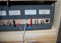
Not sure what you mean by 'any short, not just a short to ground'. The supply limits current on a dead short between the positive volts terminal to the 0 volts terminal to less than 2.2A. Here that is in action:
<snip>
Hmm good point as there isn't really any node it could short to. I was thinking for example, if you shorted to Earth (Protective Ground), what would happen.. but of course nothing would happen as the supply floats!
I did wonder though, what happens if you tie 2 channels together to get a symmetric supply, and one of the channels goes faulty...
I did wonder though, what happens if you tie 2 channels together to get a symmetric supply, and one of the channels goes faulty...
With all of the protection diodes in place (thanks again Mega 🙂 ), there isn't much that can happen. I have done some testing on it with both supplies in series and the only 'wrinkle' I can see is that the current limiter works on one channel first rather than both at the same time. This would create an asymmetrical supply, with one dropping below the other. This is an issue I'd like to fix but for now, I'll accept it as it will rarely (if ever) cause a problem.
Last edited:
OK, i guess that's not too bad. I guess now I'll explore two extra features:
* Constant Current/Constant Voltage mode light. The supply would be in CC mode if Q9 is conducting.
* Rather than current limit, a mode that as soon as the supply draws too much current, it turns off. Again I guess this can be done by checking Q9 and if it conducts too much, clamp the voltage at the A of D2 to ground.
OK, i guess that's not too bad. I guess now I'll explore two extra features:
* Constant Current/Constant Voltage mode light. The supply would be in CC mode if Q9 is conducting.
* Rather than current limit, a mode that as soon as the supply draws too much current, it turns off. Again I guess this can be done by checking Q9 and if it conducts too much, clamp the voltage at the A of D2 to ground.
The advantage of meters for both channels becomes clear when you want to set CC. With a dummy load attached, rotating the V adjust pot to the desired voltage and then rotating the I adjust to the desired current sets it up quickly. For example: 22VDC at 200mA and the supply will not exceed that current under any load conditions.
The current limit is active at all times and restricts draw to 2.2A at any voltage (with the current limit pot at max). This can be increased or decreased by changing the value of R27 and/or the sense resistor R23.
I want to replace the buz900p-buz905p on the musical fidelity a220 with irfp240-irfp9540. I will appreciate your help.
Have you thought about putting a thiele/zobel/pi/whatever network at the output to improve stability and pulse behavior? If a pulse is fast enough (in terms of slew rate), it will saturate the feedback circuitry and this may cause a long recovery time.
Also, I wonder if adaptive power limiting could be achieved using one of those analog multipliers from Analog Devices?
- keantoken
Also, I wonder if adaptive power limiting could be achieved using one of those analog multipliers from Analog Devices?
- keantoken
Have you thought about putting a thiele/zobel/pi/whatever network at the output to improve stability and pulse behavior? If a pulse is fast enough (in terms of slew rate), it will saturate the feedback circuitry and this may cause a long recovery time.
Also, I wonder if adaptive power limiting could be achieved using one of those analog multipliers from Analog Devices?
Hi Kean,
During construction, I tried many different things to stabilize the supply and finally successful with the relocation of cdom. Adding the 100uF cap to the output helped also.
Transient response is very good (see HERE) - actual scope shots of the supply in action. The slew rate looks fine to me. It is just a power supply, after all.
The current limiter has exceeded my original expectations. I had no idea it would work as well as it does and it's hard to imagine a more effective method that is as simple.
Say 1uF film, connected to output without series resistor, and tested with a square wave. Many regulated supplies will oscillate. I notice you have a 100nF cap with .3R series resistance. Some circuits may have a number of 100nF bypass, and for a lab supply to be useful it needs to be stable into these.
Just like in amplifiers, a Zobel will help with this. Maybe it is better to leave HF regulation up to capacitors near the circuit, and isolate the regulator at HF.
- keantoken
Just like in amplifiers, a Zobel will help with this. Maybe it is better to leave HF regulation up to capacitors near the circuit, and isolate the regulator at HF.
- keantoken
It is highly unlikely a 1uF cap will cause oscillation, when the 100uF cap (already in place) does not.
Like I said, the supply is stable now. Correcting the compensation through the feedback loop did it.
All of this, and other design specifics, were presented in detail earlier in the thread.
Like I said, the supply is stable now. Correcting the compensation through the feedback loop did it.
All of this, and other design specifics, were presented in detail earlier in the thread.
Film caps have MUCH lower ESR than electrolytics. Generally for electrolytics, the more F the lower ESR. The higher V the higher ESR. The larger size the lower ESR.
Having a very low ESR capacitor at the output has the effect of disconnecting the feedback loop because the output voltage no longer responds directly to a change in load or drive.
A 100uF lytic will generally have ESR>.1R. This is usually not lerge enough to goof up any regular. A film cap on the other hand has say ESR<.001R. This greatly increases the Q of any reactive network including this cap.
It doesn't sound as if you have actually tried testing the regulator with film caps. What puzzles me then is why you show a .3R resistor in series with C12. I could reason this is ESR, but I don't see it on any other cap, for instance the 100uF cap where it might be more important. If this was a film cap, then I can understand giving it ESR if it helps make the regulator stable. But if this cap needs ESR, then I don't suppose the regulator is stable into film caps.
- keantoken
Having a very low ESR capacitor at the output has the effect of disconnecting the feedback loop because the output voltage no longer responds directly to a change in load or drive.
It doesn't sound as if you have actually tried testing the regulator with film caps. What puzzles me then is why you show a .3R resistor in series with C12. I could reason this is ESR, but I don't see it on any other cap, for instance the 100uF cap where it might be more important. If this was a film cap, then I can understand giving it ESR if it helps make the regulator stable. But if this cap needs ESR, then I don't suppose the regulator is stable into film caps.
Kean,
Your first quoted statement above is incorrect.
It's plain on the schematic and the photos of the PCB that there is a film cap in place on the output - the 10nF (this, along with the 1uf in series with 300m ohm (revised to 4.7 ohms)) keep the output impedance low when the loop gain is falling off.
Would it bring you any satisfaction if I were to put a 1uF film cap across the output and photograph the results?
Would it bring you any satisfaction if I were to put a 1uF film cap across the output and photograph the results?
Here it is:
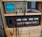
1uF cap across the output. Supply at 15VDC drawing ~1.3A:

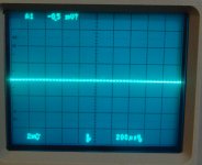
Overall view, showing scope output:

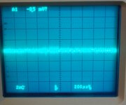
Close up of scope:

No signs of instability. The regulator is still working extremely well to maintain voltage and kill ripple (as clearly seen in the scope shot).
I hope this answers some of your questions.
My satisfaction is no prerequisite, I was only pointing out something you may want to consider and test. 10nF is not always large enough to cause oscillation. A test that would satisfy me is connecting a 1uF film cap between the terminals and testing with a square wave.
If my first statement is incorrect, I would like to know why.
I understand now that the 4.7R+1uF network is a zobel network. However if your intent is to keep output impedance reasonable at HF, hasn't the 100uF cap accomplished this? It should have lower impedance at HF than the 4.7R+1uF network. Is it possible that the increase from 300mR to 4.7R helped performance because it increased the total ESR at output?
EDIT: You posted before I did! Looks fine to me...
- keantoken
Last edited:
A test that would satisfy me is connecting a 1uF film cap between the terminals and testing with a square wave.
You mean the transient response test? That takes time to set up and I have other things to do at the moment. One of those is testing a new amp that is being powered by this supply. Pumping 10khz squarewaves through the amp near clipping has no effect whatsoever on the supply stability - that should be a reasonable test.
In all fairness and in the name of good scientific procedure, I disclose that the above scope shot was with the probe at 10x (not intentionally).
I redid the same load test, and here is the scope with the probe at 1x:

Still real clean with no discernible ripple or oscillation.
- Status
- Not open for further replies.
- Home
- Amplifiers
- Power Supplies
- Lab Power Supply Design / Build