Hello
I have assembled two L20.5 boards, measured all components and sorted the transistors according to characteristic curves. I still have the Toshiba driver transistors as selected components from my setup 10 years ago. I have also used these.
Now I have connected the boards to +-36V and the output is -34V. A high DC offset.
Since only the SMD transistor pairs were not measured, I did this with the input transistor and measured very strange curves. Both transistors (my unit says they are BJT PNP) deviate massively from each other, it looks like I got some waste.
Now of course I'm thinking of rescuing the amplifier and making a replacement input board or soldering in other components with free wiring. Any ideas on this that might work well? JFet p-channel like J175 maybe?
Update:
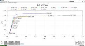
I measured the input transistor (pair) and made the following diagrams.
Because the chips don't seem to be that great and the one may not have been soldered properly as well, I replaced the input transistors with old PNP ones that I matched. The result is unchanged, a DC offset of -34V. I have no idea what is wrong there.
One point I noticed is that the Chinese 2N5401 are at hFE of 200, the ones in the kit are at 240, but my sorted out ones only have a current gain of 160. The kit transistors just have pretty non-linear behavior.
In an NHB-108 kit, the included 2N5401 and 2N5111 also have a low hFE and higher linearity, which is not wrong for music playback. But in this kit the drivers and final transistors are a horror, maybe they are just duplicates.
Attachments

My advice 1 is: purchase all semiconductors at Farnell and use them without exception. 2N5401 , 2N5551(swap base and collector), NJW0302, NJW0281. Use Wima and Panasonic capacitors. Perhaps diodes too. (5401 in the kit had almost 300hfe, 5551 had 112).Hello
I have assembled two L20.5 boards, measured all components and sorted the transistors according to characteristic curves. I still have the Toshiba driver transistors as selected components from my setup 10 years ago. I have also used these.
Now I have connected the boards to +-36V and the output is -34V. A high DC offset.
Since only the SMD transistor pairs were not measured, I did this with the input transistor and measured very strange curves. Both transistors (my unit says they are BJT PNP) deviate massively from each other, it looks like I got some waste.
Now of course I'm thinking of rescuing the amplifier and making a replacement input board or soldering in other components with free wiring. Any ideas on this that might work well? JFet p-channel like J175 maybe?
Advice 2: dump the NHB-108 into the first trash-can, it isn't worth.
PS1: Have you noticed these very small ICs on the board? What if the problem is there?
PS2: they sell a single channel version too. Guess why 😉
PS3: You can purchase 2SC5171, 2SD669 (don't forget to isolate it from the heat sink) and 2SA1930 transistors at Reichelt.de. Not originals, but at least reputation of Reichelt.de gives some confidence.
Last edited:
Hello Berlusconi,
I have matched the 2SC5171 and 2SA1930 and installed some with almost identical hFE.
The curves above are from the mini devices - small ICs - soldered to the boards, which are pnp transistor pairs. I removed these ICs on a couple of L20.5 and replaced them with normal audio pnp transistors.
I am surprised about the DC offset, as all components are measured. I have not soldered any Panasonic capacitors in this kit, but that cannot be the reason for the DC offset.
Another question:
You write that the NHB-108 is good for the trash basket - did you build it with balanced transistors - without this distortion via the DC offset at the input? I think that the ON MJE1503x are very unsuitable for this amplifier and the MJL3281 / MJL1302 are not optimal. With my old amplifiers I compensated the differences between the PNP and NPN transistors by the resistors, so that they have a DC offset in the mV range. That would also be my goal with the NHB-108. Of course, it won't be an NHB any more, but I'm also an opponent of class A amplifiers, as they usually introduce sound colouration and often just sound like transistors.
Hi Tim,Hello Berlusconi,
...Another question:
You write that the NHB-108 is good for the trash basket - did you build it with balanced transistors - without this distortion via the DC offset at the input? I think that the ON MJE1503x are very unsuitable for this amplifier and the MJL3281 / MJL1302 are not optimal. With my old amplifiers I compensated the differences between the PNP and NPN transistors by the resistors, so that they have a DC offset in the mV range. That would also be my goal with the NHB-108. Of course, it won't be an NHB any more, but I'm also an opponent of class A amplifiers, as they usually introduce sound colouration and often just sound like transistors.
I have worked a lot on the NHB-108 but it never had good sound at more than few watts. Now after measuring frequency response, I understand why: the amplifier has high distortion and more importantly both odd and even. This happens equally with and without the DC servo connected. Otherwise, bandwidth and square wave are great.
An article "darTZeel NHB-108 Model One power amplifier Measurements" states that:
It is interesting that an article doesn't go much in detail regarding this important issue. PR perhaps.Again due to its lack of loop negative feedback, the NHB-108 is not a low-distortion design.
I am puzzled why people pay for that such a ridiculously (or should I say insanely) high price. Financial masochists, perhaps. 😉
L20.5 sounds way much better than NHB-108.
Last edited:
Today I was lucky as I have avoided destruction of my speakers. 😉🙂
For these concerned a quick info: L20.5 boards have very short life expectancy. For some arbitrary reason they simply unceremoniously stop working, forever. Today I've tested one pair and the initial results were indeed pleasant, but as soon as I've increased power there was smoke coming from one of 5401s and the output swung to 42V. Fortunately, I was cautious enough to use a dummy load, otherwise this could have burned my speakers too. I have tried by changing everything but it seems that these mysterious little on-board ICs stopped working so the only resolution is to order yet another board. I guess that's the reason they also sell a single channel too. I'm afraid they know what's going on and happily accept the failure of their own product as yet another "business opportunity". They simply don't care, turnover must increase as long as nobody knows.
I'm finished with the Poor Man's High-End amplifiers all together. All LJM boards have flown today into the trash-bin, including the still working L12-2. Pity, they all measured fine but are totally unreliable. I'm not the only one who experienced this, just look around and you may find similar conclusions. You may also find that the "single channel" boards are selling quite well.
Otherwise, it was fun playing with these midgets.🙂
Take care!🙂
"these mysterious little on-board ICs stopped"
Nobody can figure out what those IC's are?
Thanks guys,most likely - dual smd transistors 5401 or 5551
My point was, however, that these boards are irreparably useless, regardless to reasons. You may either push it a bit harder (in my case it was 30W, I have been measuring it ) or it spontaneously starts wildly oscillating for some unpredictable reason, it will sooner or later die without good reason and you will have to buy new, again and again. I consider this utterly unfair practice.
Just one seller/producer was worse than this. Someone was selling KSA-50 boards with wrong zener connection. The amplifier died whether you've soldered it correctly or not.
I am in business for decades without having a business card because I work opposite to this rabid business model: I work dependably and safely, for the interest of the client. My clients are prepared to pay multiply higher prices for my services. I don't have to seek new victims because I care for clients.
For these on-line pirates, clients are an endlessly large bunch of fools - they count on enough large number of new victims. Fortunately, this one is cheap.
There is nothing "High-End" here. Just the bottom of quality. Not to mention ethics.
"these mysterious little on-board ICs stopped"
Nobody can figure out what those IC's are?
I did measure the chips in the input ( #102), which is a BJT PNP pair. The others can not be measured. I assume that these chips only came as copyright on the boards, so that they can be sold better without the next one copying them.
Has anyone ever simulated the L20.5?
Thanks Timoty 🙂... I assume that these chips only came as copyright on the boards, so that they can be sold better without the next one copying them.
Does this mean that these ICs have no function and can be safely removed?
But this "IP protective measure" hurts clients even more by preventing troubleshooting this otherwise technically extremely weak product.
Have you repaired your board with almost identical failure?

no, I have not been able to successfully repair the 20.5 yet. After the last few posts, the point of doing so is also disappearing. I've spent too much time on this already, it's just frustrating.
I didn't mean that the dual transistors on the boards are unnecessary, but if they were also large components, then everyone can identify what it is. Then it would be easy to change them and there would be no ominous black crumbs...
I didn't mean that the dual transistors on the boards are unnecessary, but if they were also large components, then everyone can identify what it is. Then it would be easy to change them and there would be no ominous black crumbs...
Las dich nicht enttäuschen! (don't let that disappoint you)no, I have not been able to successfully repair the 20.5 yet. After the last few posts, the point of doing so is also disappearing. I've spent too much time on this already, it's just frustrating.
I didn't mean that the dual transistors on the boards are unnecessary, but if they were also large components, then everyone can identify what it is. Then it would be easy to change them and there would be no ominous black crumbs...
This board costs like a couple of good Bayerisches beer, nothing more. To further comfort you: I have burnt three of them and I plan to to push the last a bit harder, to see it smoldering.


However, I think that this kind of mortality of these board isn't coincidence.
Also, statements that these mysterious ICs are just IP protection meassure are pure speculation. Any professional could easily reveal the design. This isn't spaceship, just ordinary simple amplifier board based on Douglass Self design ideas.
BTW, there are fine boards arround. You just have to seek and pick the right one, and that will not cost you that much.
Good luck 🙂
I have some other LJM boards (L20V9 I think) and they also have the SMD IC, and there it is used for the input CCS.

Hi DaveFred,
I had ten of these boards all blow I binned five of them and then decided to rebuild the boards which I had left all of them work fine at the moment but the part you are pointing to is still the original part and has never been changed so I don't think this is the problem.
Bill
I had ten of these boards all blow I binned five of them and then decided to rebuild the boards which I had left all of them work fine at the moment but the part you are pointing to is still the original part and has never been changed so I don't think this is the problem.
Bill
Hi DaveFred,
I had ten of these boards all blow I binned five of them and then decided to rebuild the boards which I had left all of them work fine at the moment but the part you are pointing to is still the original part and has never been changed so I don't think this is the problem.
Bill
What parts blew?
Any idea what the mystery part is? The markings have been sanded off!
Hi DaveFred,
When the boards actually blew, despite the noise and bright lights actual damage was very little. Interestingly though all the parts that blew was the same on all the boards but on a couple some of the R050 resistors blew. The two 68ohm resistors that are closest to one of the R050 resistors are what always blow along with one or two of the power transistors. I made it a priority to replace all of the power transistors so I could make sure they were as matched as I could make them. I also replaced all of the R050 resistors even though most of them were still working and measuring fine. I will be honest here I could only buy a batch of 200 R050 resistors so I decided to use them in the interests of making the board a little more reliable. I only use a 400va 25-0-25volt ac transformer which means I top out at around 35 to 37 dc volts and so far I have had no more problems. I also did the modifications Berlusconi suggested and I do believe that helped a lot. I use two 400va transformers.
When the boards actually blew, despite the noise and bright lights actual damage was very little. Interestingly though all the parts that blew was the same on all the boards but on a couple some of the R050 resistors blew. The two 68ohm resistors that are closest to one of the R050 resistors are what always blow along with one or two of the power transistors. I made it a priority to replace all of the power transistors so I could make sure they were as matched as I could make them. I also replaced all of the R050 resistors even though most of them were still working and measuring fine. I will be honest here I could only buy a batch of 200 R050 resistors so I decided to use them in the interests of making the board a little more reliable. I only use a 400va 25-0-25volt ac transformer which means I top out at around 35 to 37 dc volts and so far I have had no more problems. I also did the modifications Berlusconi suggested and I do believe that helped a lot. I use two 400va transformers.
What parts blew?
Any idea what the mystery part is? The markings have been sanded off!
The two parts you are referring to are actually NPN JFETS they have no model number but are similar to 2N5565. I don't know if this is of any help but I hope someone with more knowledge than me can take this a bit further.
Hello friends,
Meanwhile, I have spoken to Billy and I must say, this was a fruitful exchange. He has explained me the nature of the problem and possible solutions.
Now, please, refer to the schematic in post #3.
To repair the damaged board or improve its reliability, you have to:
1. Replace R13 and R20 with higher resistance
2. Replace the yellow 104 capacitor with something better.
I have successfully recovered one of the boards by replacing resistors with what I had available: quality 0R22/7W and much better 104 capacitor.
I have also re-soldered and tested all output transistors. One transistor was damaged and one 01R resistor has shown megaohm resistance.
I have tested the bord on dummy load at low wattage and it works now.
The lesson learned: something causes sudden high current inrush into the output stage and it usually damages one half of the output. The result is extremely high voltage at the output, almost the value of the rail.
I suggest cautious evaluation of the board before connecting it to the speakers because this kind of failure would most probably destroy your speakers.
I have also tried to repair yet another board but this time I couldn’t apply the same cure. Measurements at the bases of the output transistors indicate that the signal doesn’t reach the output stage, indicating that the problem must have been somewhere in the previous stages. I might get back to this problem later on.
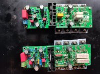
Below you may observe at the snapshot below one board without modification and the other after the repair. All credit for the presented method go to Billy, I just followed his instructions.
I wish you all a pleasant Sunday afternoon.
Meanwhile, I have spoken to Billy and I must say, this was a fruitful exchange. He has explained me the nature of the problem and possible solutions.
Now, please, refer to the schematic in post #3.
To repair the damaged board or improve its reliability, you have to:
1. Replace R13 and R20 with higher resistance
2. Replace the yellow 104 capacitor with something better.
I have successfully recovered one of the boards by replacing resistors with what I had available: quality 0R22/7W and much better 104 capacitor.
I have also re-soldered and tested all output transistors. One transistor was damaged and one 01R resistor has shown megaohm resistance.
I have tested the bord on dummy load at low wattage and it works now.
The lesson learned: something causes sudden high current inrush into the output stage and it usually damages one half of the output. The result is extremely high voltage at the output, almost the value of the rail.
I suggest cautious evaluation of the board before connecting it to the speakers because this kind of failure would most probably destroy your speakers.
I have also tried to repair yet another board but this time I couldn’t apply the same cure. Measurements at the bases of the output transistors indicate that the signal doesn’t reach the output stage, indicating that the problem must have been somewhere in the previous stages. I might get back to this problem later on.
Below you may observe at the snapshot below one board without modification and the other after the repair. All credit for the presented method go to Billy, I just followed his instructions.
I wish you all a pleasant Sunday afternoon.
Attachments
- Home
- Amplifiers
- Solid State
- L20.5 AP SYS Test data My design