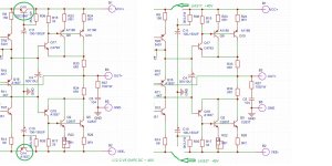
The CFP structure has the best thermal stability in the world. If you can understand this structure.
Just tighten the two 2SA1837 screws on the circuit board.
If static current changes with temperature. It's obvious. The screw of A 1837 is not tightened.
Just get some silicone grease.
Additionally. Regardless of whether the power transistor is ON SANKEN. or Toshiba. There is no difference at all.
But the power tube needs to be installed on the radiator.
Add measurement images. business as usual. There is no instability.
Attachments
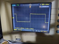
There is no instability
I do aggree. LJM has invested in this new version and we should investigate this responsibly and carefully. In todays' environment there are so many HF signals that may affect measurements. I suspect that these "oscillations" might originate from environment, not from the design itself. Recently I had a similar situation: another Blameless amp had HF oscillations at the inflection point at 0 V, but eventually I have found out that it was induced from elsewhere.@Tolik: Stay tuned to that channel...
Despite "warnings" I will order Ver. 5 board and investigate. There is almost nothing to lose here: just about 30 EUR. Breakfast & a cup of coffee.. Why not. LJM can lose a lot and I don't want let it happen without a good reason.
So, lets stay tuned...

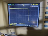
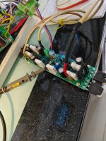
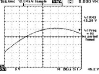
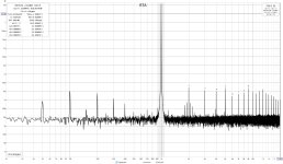
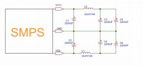
So L12-2 V5 (Toshiba transistors) with linear PSU. The transformer is 400W 2x37V 2x2.7A rated. The filter is 3x22000uF per rail JCCON caps.
The bias was checked after powering on as 3.2mV (last time it was set to 5 mV), was adjusted to 5mV, and then the amplifier was preheated with 1W output power for 30min. then bias was adjusted again. During tests, bias floated 5-15mV. The amplifier module was tested on a 200x70x30mm heatsink. While 8Ohm load tests, the heatsink became pretty hot, and testing at 4Ohm was impossible without a fan. So take care while purchasing the "recommended" heatsink on Aliexpress, that even smaller than I used.
Ewen with a 400W supply, V5 can't deliver the 120 clean Watts promised.
Do I going to power my new MoFi 888 with that amp - no. Regardless of THD figures. Amp should be stable with SMPS, bias should not float. And my Wolverine modules have arrived...
Attachments
Last edited:
Why “oscillations” not originating from v4 boards? Same environment, same signal source, same power supply?"oscillations" might originate from environment, not from the design itself.
When I heard about instability of V5, I still trust in LJM designs and decency, and ordered v4.2. It’s arrived already. So I’ll be able to check it out in same environment as v4 and 5.
The thing that LJM should to loose, it is a confidence, that his clients are stupid, and unable to afford measurement instruments.
Maybe because v5 has more sensitive input stage. Maybe...Why “oscillations” not originating from v4 boards? Same environment, same signal source, same power supply?
V4.2 will not be better. But the V4.2 input transistor has a voltage regulator diode. There is a 5V6 diode.Why “oscillations” not originating from v4 boards? Same environment, same signal source, same power supply?
When I heard about instability of V5, I still trust in LJM designs and decency, and ordered v4.2. It’s arrived already. So I’ll be able to check it out in same environment as v4 and 5.
The thing that LJM should to loose, it is a confidence, that his clients are stupid, and unable to afford measurement instruments.
It can avoid high-frequency oscillations generated by SMPS. And V5 does not have this voltage regulator diode.
But if we don't use SMPS. V5 would be better. Because V5 adopts CFP input structure.
V4.2 will have a DC output of approximately 20MV. And V5 usually only has 0.1-3MV.
Why do I determine that high-frequency oscillation is the cause of SMPS.
It's simple. Because 99% of analog power amplifiers in the world using SMPS will have the same problem.
Because SMPS does not output DC voltage. But it outputs a voltage with high-frequency PWM components.
I have encountered over a hundred clients with this issue. They use different power amplifiers. There is TDA 7293. LM3886
MX50。 So this is a very common phenomenon. You just don't know it yourself.
L12-2 VER 4.2 has a voltage regulator circuit as its input. So it's just that this situation won't happen.
Additionally. Different testing instruments. Test the same amplifier. THD is not the same.
Because the tester itself also generates THD.
Relatively speaking. The higher the level of testing equipment. The THD result of the test will be lower. APSYS 2 can basically measure smaller THD
In fact, SMPS of today, can outperform linear PSU in terms of ripple and noise, by controlling rice/fall time of the pulses. LT even released a series of special controllers for low noise SMPS.Because SMPS does not output DC voltage. But it outputs a voltage with high-frequency PWM components.
Than LLC SMPS, that does not use PWM at all, and operates on sine waves.
Take a look at Benchmark ahb2 amp, Topping b200, Wolverine that powered with SMPS, that outperforms any L12-2 in any aspect, other than price.
I think that the ability of the amp, to be powered by SMPS, is an excellent thing. It allows to use cheaper compact enclosures, built amplifier lightweight, avoid expensive transformers and capacitors, made whole designs more energy effective and environment friendly.
Why to avoid all positive above? At your place, I was thinking about V5.2, that fully SMPS compatible.
About the bias. At 60-70ma bias, the THD drops below 0.005%, it is also a place for some improvement.
The noise and overall THD are good,
just increase PSRR ( SMPS compatibility ) and tweak bias for a bit more stability and lower THD. Amp will be perfect. I’ll be happy to spend even $100 for pair of such modules.
The input stage should be sensitive to input signal, instead of power rail ripple.Maybe because v5 has more sensitive input stage.
There is PSRR parameter, that characterizes the ability of an amplifier to reject noise and ripple of power supply, and not allow it to mix with the signal.
Capacity multipliers are supposed to additionally increase PSRR by rejecting a ripple approaching input stages. I was shocked while I saw, that such amp unable to work with really good SMPS
If LJM can’t or don’t want to add SMPS capabilities to his amps, he should to force every seller, who sells his modules, clearly warn clients, about restriction of SMPS with certain LJM amplifiers
Last edited:
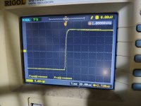
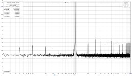
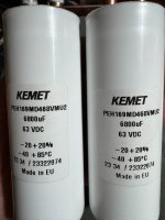
high-frequency PWM components of LLC SMPS that operate on the FM principle. Well, if there are "PWM components", then there is a special solution, to manage them. There are power capacitors, specially designed to filter out the products of high dI/dT processes in SMPS. KEMET PEH169 caps are among the champions in this league. Let's see if LJM was correct when he talked about "PWM components", and what is capable of great caps.
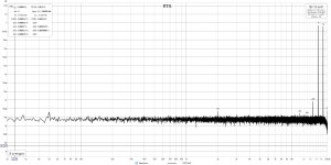
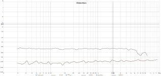
The noise floor isn't great like with linear PSU, but still at good -103dbfs/A
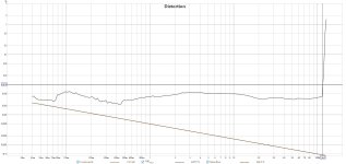
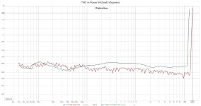
Power output - up to 134W within 0.004% THD. Great, inexpensive SMPS outperforms linear PSU with a 100-euro transformer.
Ripple - IT'S NOT HERE ANYMORE. There is no need for reworks proposed by Michael Benny. Just PROPER filtering. LJM was right when told that V5 can't tolerate SMPS noise. I was correct also when I told V5.2 should be able to work with SMPS. Hope LJM will hear, and make L12-2 great again.
Each thing has its drawbacks, and my approach is taken here, not an exception. So minuses of those caps are:
The price of ultra-low ESR ESL is Lifespan. It is shorter than 20,000 hours of Vishay caps.
The price is $29.90 per cap.
The SMPS should be able to charge a massive power bank. That's all.
The noise floor isn't great like with linear PSU, but still at good -103dbfs/A
Power output - up to 134W within 0.004% THD. Great, inexpensive SMPS outperforms linear PSU with a 100-euro transformer.
Ripple - IT'S NOT HERE ANYMORE. There is no need for reworks proposed by Michael Benny. Just PROPER filtering. LJM was right when told that V5 can't tolerate SMPS noise. I was correct also when I told V5.2 should be able to work with SMPS. Hope LJM will hear, and make L12-2 great again.
Each thing has its drawbacks, and my approach is taken here, not an exception. So minuses of those caps are:
The price of ultra-low ESR ESL is Lifespan. It is shorter than 20,000 hours of Vishay caps.
The price is $29.90 per cap.
The SMPS should be able to charge a massive power bank. That's all.
Attachments
Last edited:
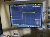
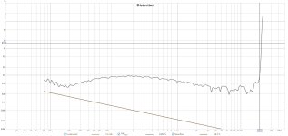
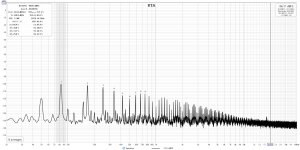
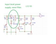
During continuing research on how to fix the side effects of LJM's attempt to squeeze every last coin from his latest creature, by omitting several cheap, yet important components, and compromising the quality of his product, I came across the idea to follow one old good document, released by Ridley Engenirreng. Dr Ridley suggested a simple way to reduce output SMPS noise: C-L-C filter. I found suitable 10uH inductors. 10uH is a bit low, but enough to see if the idea is working at all. To make things perfect, I added 2x5.6uF MKP.
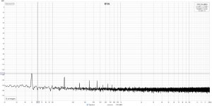
First I added MKP and the noise was reduced by nearly 3dB, then I connected inductors and got the next -5dB, a total of -111dBfs/A
I noticed an interesting effect: the noise floor, just after powering the amplifier on, was 97-98dBfs, the number increased slowly, and after either 5-6 minutes, it stopped at -103dB (MKP and inductors were still not added) Just like a tube, or massive class A amp, and of course not due to bias instability. I repeated the cooling-heating cycle, with the signal applied to the input of the amp, and monitoring of THD. 0.009% THD dropped to 0.003% after the same 5-6 min. I remember and trust in LJM's words - "bias is stable".
The total cost of the filter, assembled by point-to-point wiring, (not including PCB) - near $80. Just like 3 sets of L12 V5. Just because somebody saved on the coin-priced components.
I think there was enough effort was spent on that junk board, created in an attempt to squeeze instead of improve the design.
I recommend avoiding L12-V5 until bias and PSRR issues are fixed. I recommend STRICTLY avoiding L12-V5 usage with SMPS of any kind.
The next DUT is L12-4.2 Stay tuned...
First I added MKP and the noise was reduced by nearly 3dB, then I connected inductors and got the next -5dB, a total of -111dBfs/A
I noticed an interesting effect: the noise floor, just after powering the amplifier on, was 97-98dBfs, the number increased slowly, and after either 5-6 minutes, it stopped at -103dB (MKP and inductors were still not added) Just like a tube, or massive class A amp, and of course not due to bias instability. I repeated the cooling-heating cycle, with the signal applied to the input of the amp, and monitoring of THD. 0.009% THD dropped to 0.003% after the same 5-6 min. I remember and trust in LJM's words - "bias is stable".
The total cost of the filter, assembled by point-to-point wiring, (not including PCB) - near $80. Just like 3 sets of L12 V5. Just because somebody saved on the coin-priced components.
20mV offset is acceptable even for headphone amplifiers. So this is not a reason to compromise PSRR.V4.2 will have a DC output of approximately 20MV. And V5 usually only has 0.1-3MV.
I think there was enough effort was spent on that junk board, created in an attempt to squeeze instead of improve the design.
I recommend avoiding L12-V5 until bias and PSRR issues are fixed. I recommend STRICTLY avoiding L12-V5 usage with SMPS of any kind.
The next DUT is L12-4.2 Stay tuned...
Attachments
Last edited:
Different SMPs are different. Do not compare different amplifiers using SMPS with L12-2.high-frequency PWM components of LLC SMPS that operate on the FM principle. Well, if there are "PWM components", then there is a special solution, to manage them. There are power capacitors, specially designed to filter out the products of high dI/dT processes in SMPS. KEMET PEH169 caps are among the champions in this league. Let's see if LJM was correct when he talked about "PWM components", and what is capable of great caps.
The noise floor isn't great like with linear PSU, but still at good -103dbfs/A
Power output - up to 134W within 0.004% THD. Great, inexpensive SMPS outperforms linear PSU with a 100-euro transformer.
Ripple - IT'S NOT HERE ANYMORE. There is no need for reworks proposed by Michael Benny. Just PROPER filtering. LJM was right when told that V5 can't tolerate SMPS noise. I was correct also when I told V5.2 should be able to work with SMPS. Hope LJM will hear, and make L12-2 great again.
Each thing has its drawbacks, and my approach is taken here, not an exception. So minuses of those caps are:
The price of ultra-low ESR ESL is Lifespan. It is shorter than 20,000 hours of Vishay caps.
The price is $29.90 per cap.
The SMPS should be able to charge a massive power bank. That's all.
Because some SMPS outputs a DC voltage closer to that of the battery. Some SMPS outputs have high high-frequency interference. This is not related to the amplifier itself.
There are rarely significant differences between different circular transformers. But there are significant differences among different SMPSs. SMPS with the same power may have a price difference of more than ten times.
Many SMPS, especially DIY SMPS products, are unqualified. This is quite common. They lack filtering capacitors. Filter inductor.
Adding CLC can avoid this situation.
Relatively speaking, the output ripple voltage of SMPS with higher operating frequencies will be lower. There is less interference.
Alternatively, a voltage regulator and a three pole current expansion circuit can be used. Provide power to the power amplifier.
All these plans. Suitable for all SMPS+AMP solutions. It's not just related to L12-2. Most SMPSs have the same issue.
You can also modify the input level power supply module of L12-2. Add LM317.337 for separate voltage regulation power supply. Provide separate power supply to the input stage.
Attachments
You should modify this sentence to. Try to avoid using all analog power amplifiers as much as possible when using SMPS.During continuing research on how to fix the side effects of LJM's attempt to squeeze every last coin from his latest creature, by omitting several cheap, yet important components, and compromising the quality of his product, I came across the idea to follow one old good document, released by Ridley Engenirreng. Dr Ridley suggested a simple way to reduce output SMPS noise: C-L-C filter. I found suitable 10uH inductors. 10uH is a bit low, but enough to see if the idea is working at all. To make things perfect, I added 2x5.6uF MKP.
First I added MKP and the noise was reduced by nearly 3dB, then I connected inductors and got the next -5dB, a total of -111dBfs/A
I noticed an interesting effect: the noise floor, just after powering the amplifier on, was 97-98dBfs, the number increased slowly, and after either 5-6 minutes, it stopped at -103dB (MKP and inductors were still not added) Just like a tube, or massive class A amp, and of course not due to bias instability. I repeated the cooling-heating cycle, with the signal applied to the input of the amp, and monitoring of THD. 0.009% THD dropped to 0.003% after the same 5-6 min. I remember and trust in LJM's words - "bias is stable".
The total cost of the filter, assembled by point-to-point wiring, (not including PCB) - near $80. Just like 3 sets of L12 V5. Just because somebody saved on the coin-priced components.
20mV offset is acceptable even for headphone amplifiers. So this is not a reason to compromise PSRR.
I think there was enough effort was spent on that junk board, created in an attempt to squeeze instead of improve the design.
I recommend avoiding L12-V5 until bias and PSRR issues are fixed. I recommend STRICTLY avoiding L12-V5 usage with SMPS of any kind.
The next DUT is L12-4.2 Stay tuned...
Including LM3886 LM49810. Because they yield the same results as L12-2.
Additionally. Not all SMPSs have the same problem. For example. ASTEC, Delta, SMPS is very good.
Don't always categorize problems as L12-2 problems. This is why your SMPS output is very high. High frequency interference. That's it.
In fact, the input stage power supply of L12-2 V5 has exceeded 95% of the power amplifier modules.
It adopts the method of transistor+filtering capacitor. In theory, it is equivalent to using two 10000 UF capacitors separately for the input stage.
Attachments
Last edited:
I know the possibility of providing a separate supply to the input stages, and I know IC better than 317/337, specially designed to deal with SMPS output voltage. The question is why do I need it at all? Why do buyers have to pay for your attempt to cut the price of the board? Why do the sellers of 12-5 not warn buyers about SMPS incompatibility? It is so expensive to return the zener diode and cap? It is so difficult to add "DO NOT USE WITH SMPS" in the description?Alternatively, a voltage regulator and a three pole current expansion circuit can be used. Provide power to the power amplifier.
All these plans. Suitable for all SMPS+AMP solutions. It's not just related to L12-2. Most SMPSs have the same issue.
You can also modify the input level power supply module of L12-2. Add LM317.337 for separate voltage regulation power supply. Provide separate power supply to the input stage.
It's impossible to fix bias walking?
What's next? Single-ended V6, with one output device, because 20-30W of output power is OK for comfortable listening level, on most loudspeakers, in most apartments?
The amount of the modifications proposed to V5 is enough, to build another amplifier already. So what do we need V5 for?
Thell it to Benchmark Media, or Jeff Rowland, or Ostripper. Those dudes are not educated enough and still don't know about your SMPS restriction, so they continue to design SMPS-compatible amplifiers. Tell it to designers of all car audio, and professional concert amplifiers. Help them, make the world better.Try to avoid using all analog power amplifiers as much as possible when using SMPS.
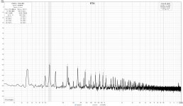
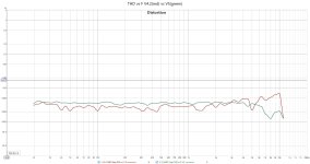
V4.2 measurements and brief comparison to V5.
Noise floor: V5 show no advantage with LPS over v4.2, while with SMPS V4.2 is the clear winner with 114-117dBfs vs 103dBfs of V5
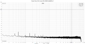
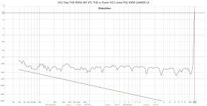
THD: V4.2 Linear PSU 400W 2x66000 uF at its best.
Efficiency: V4.2 is the clear winner.
IMD: V5 does not show superiority
So V4.2 works perfectly with the bare SMPS, with no additional filter, while V5 asks for low-noise SMPS or Linear PSU.
Let's see the price list.
Transformer used
https://sklep.toroidy.pl/en_US/p/TTSA0400-Transformer-AUDIO-TSA400VA-voltage-to-50V-/318
$90 not including shipping and tax, need 2 pcs
Rectifier board and capacitors
https://www.aliexpress.com/item/100...st_main.5.7e9818023CFl8C&gatewayAdapt=glo2vnm
$7.8 x 6 per channel = $46.8
https://www.aliexpress.com/item/100...o.order_list.order_list_main.4.7e981802Y2OypW
$20 per channel
-------- Total $266 for dual mono. $176 for single transformer dual mono, $133 for 1 transformer and 1 rectifier ----
SMPS 500W
https://www.aliexpress.com/item/100....order_list.order_list_main.58.7e981802Y2OypW
$34 for stereo or $68 for dual mono, with close to 140W per channel.
SMPS +V4.2 working well even with no additional filter.
Why do we need to pay that extra in the case of V5? - Probably to allow LJM to save almost $1 on the Zener diode, small capacitor, and pair of small signal transistors. Is it possible to solve the problems of V5? - Yes, the designer should understand, that fine measurement instruments are available and affordable even to housewives today. And each step, each attempt to sell the snake oil, can be validated easily.
Noise floor: V5 show no advantage with LPS over v4.2, while with SMPS V4.2 is the clear winner with 114-117dBfs vs 103dBfs of V5
THD: V4.2 Linear PSU 400W 2x66000 uF at its best.
Efficiency: V4.2 is the clear winner.
IMD: V5 does not show superiority
So V4.2 works perfectly with the bare SMPS, with no additional filter, while V5 asks for low-noise SMPS or Linear PSU.
Let's see the price list.
Transformer used
https://sklep.toroidy.pl/en_US/p/TTSA0400-Transformer-AUDIO-TSA400VA-voltage-to-50V-/318
$90 not including shipping and tax, need 2 pcs
Rectifier board and capacitors
https://www.aliexpress.com/item/100...st_main.5.7e9818023CFl8C&gatewayAdapt=glo2vnm
$7.8 x 6 per channel = $46.8
https://www.aliexpress.com/item/100...o.order_list.order_list_main.4.7e981802Y2OypW
$20 per channel
-------- Total $266 for dual mono. $176 for single transformer dual mono, $133 for 1 transformer and 1 rectifier ----
SMPS 500W
https://www.aliexpress.com/item/100....order_list.order_list_main.58.7e981802Y2OypW
$34 for stereo or $68 for dual mono, with close to 140W per channel.
SMPS +V4.2 working well even with no additional filter.
Why do we need to pay that extra in the case of V5? - Probably to allow LJM to save almost $1 on the Zener diode, small capacitor, and pair of small signal transistors. Is it possible to solve the problems of V5? - Yes, the designer should understand, that fine measurement instruments are available and affordable even to housewives today. And each step, each attempt to sell the snake oil, can be validated easily.
Attachments
I have this one and it is noisy
https://www.aliexpress.com/item/100...ZATcIy0P&utparam-url=scene:search|query_from:
https://www.aliexpress.com/item/100...ZATcIy0P&utparam-url=scene:search|query_from:
Yes, -114dBfs is an excellent result, just pay attention to the ground, but it is simple.is the 4.2 quiet with the smps you linked?
I tested that SMPS with v4 also, with no issue.
- Home
- Amplifiers
- Solid State
- L12-2 CFP Output amp 120W*2 8R