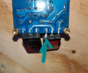
I think there could be a problem. You can de-solder it and measure with diode tester on a multimeter to see if there is still connection to the leg.
They are not mosfets, they are BJT transistors.
They are not mosfets, they are BJT transistors.
Hi Rallyfinnen,
You just taught me it's a BJT rather than a Mosfet, that's perfect for me.
I will take your advice, I will desolder it and test it with a multimeter.
You just taught me it's a BJT rather than a Mosfet, that's perfect for me.
I will take your advice, I will desolder it and test it with a multimeter.
I desoldered the transistor and measured it. I have a question about the measurements.
The BJT C2837 is an NPN, I get the same resistor with red wire on the base and black wire on the collector and then the emitter.
On the other hand if I put the black on the base and the red wire on the collector or the emitter, I get no value.
Is this normal ??
The BJT C2837 is an NPN, I get the same resistor with red wire on the base and black wire on the collector and then the emitter.
On the other hand if I put the black on the base and the red wire on the collector or the emitter, I get no value.
Is this normal ??
I desoldered the transistor and measured it. I have a question about the measurements.
The BJT C2837 is an NPN, I get the same resistor with red wire on the base and black wire on the collector and then the emitter.
On the other hand if I put the black on the base and the red wire on the collector or the emitter, I get no value.
Is this normal ??
How to Test NPN & PNP Transistor - Leets academy
Different idle currents
Hi, There is 0.3mv difference between positive and negative power transistors idle currents. One is 0.5mv for example and the other 0.8mv over 0.1 ohm resistors (R13,R20). I changed the idle current, difference is the same 0.3mv.
what do you think about that?
Hi, There is 0.3mv difference between positive and negative power transistors idle currents. One is 0.5mv for example and the other 0.8mv over 0.1 ohm resistors (R13,R20). I changed the idle current, difference is the same 0.3mv.
what do you think about that?
Hi all,
I have tested the transistor, it works.
I have a tested one channel, I have the other one left and the wiring has to be finalized.
As soon as it is tested on my channel, I will get back to you with my impressions and some photos.
Denis
I have tested the transistor, it works.
I have a tested one channel, I have the other one left and the wiring has to be finalized.
As soon as it is tested on my channel, I will get back to you with my impressions and some photos.
Denis
Hi everyone,
I have finished.
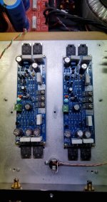
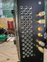
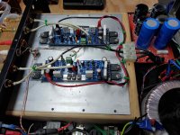
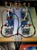
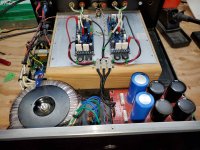
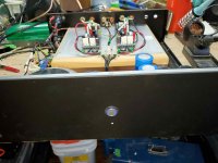
I must say at the outset that the original amplifier (a Goldmund clone) was fitted by Pinnochio. But this Goldmund clone was not good for me, so I replaced the PCBs with the L12.2s and changed the wiring.
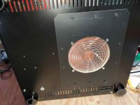
The rectification is provided by 2 diode bridge and 108,000uf total for the two rails. The power supply is a 500va. The DC voltage is 47vdc. The radiator is at the bottom and below there is a very quiet Noctua fan, the air is propelled behind the case. I did a quick listen on my workshop fullrange and the sound seems very good. No background noise, it's very quiet.
Tomorrow I plug into my main channel and will get back to you with a little review. I have 2 other amplifiers which are currently in testing.
I like this.
I have finished.
I must say at the outset that the original amplifier (a Goldmund clone) was fitted by Pinnochio. But this Goldmund clone was not good for me, so I replaced the PCBs with the L12.2s and changed the wiring.
The rectification is provided by 2 diode bridge and 108,000uf total for the two rails. The power supply is a 500va. The DC voltage is 47vdc. The radiator is at the bottom and below there is a very quiet Noctua fan, the air is propelled behind the case. I did a quick listen on my workshop fullrange and the sound seems very good. No background noise, it's very quiet.
Tomorrow I plug into my main channel and will get back to you with a little review. I have 2 other amplifiers which are currently in testing.
I like this.
Attachments

Last edited:
Hi,
My boards are on the way and during that I would like to order transformer as well. How much power do I need? As I understand higher voltage on rail - higher power of transformer I need? I plan to get either Hammond 300va 30v or Antek ones(300va 34v, 400va 34v). There is not a big difference in price when you buying that power rating. I just don't want to make mistake in choosing one. So far I received only soft start and rectifier board.
Still haven't decided what capacitors to use. I am thinking about 8200uf 71v Nichicon LKS series. It would be 24,600uf per rail.
All this will go into chassis from old multiroom amplifier.
For now I have only bookshelf speakers. Not in need of big power- just something that plays better than my current setup. Thanks
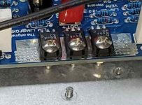
Hi Andersonix ,
No they're not too long. This is because when the PCB is tight, these 3 screws touch the radiator in order to transmit the heat released by the transistors to the radiator.
No they're not too long. This is because when the PCB is tight, these 3 screws touch the radiator in order to transmit the heat released by the transistors to the radiator.
Hi,
My boards are on the way and during that I would like to order transformer as well. How much power do I need? As I understand higher voltage on rail - higher power of transformer I need? I plan to get either Hammond 300va 30v or Antek ones(300va 34v, 400va 34v). There is not a big difference in price when you buying that power rating. I just don't want to make mistake in choosing one. So far I received only soft start and rectifier board.
Still haven't decided what capacitors to use. I am thinking about 8200uf 71v Nichicon LKS series. It would be 24,600uf per rail.
All this will go into chassis from old multiroom amplifier.
For now I have only bookshelf speakers. Not in need of big power- just something that plays better than my current setup. Thanks
Take a 400va 34v transformer especially if you plan to use medium efficiency and 4 ohm columns in the future.
It all depends on your listening needs. With 8 ohms speakers, 300va would be sufficient, but if the price is not important and you bought a new transformer, go with a 400va 34v (30va will not give the maximum power).
24,600uf per rail is very sufficient. I can not help you with the choice of capacitors. Also consider using hp protection. In my case I have one outside.
https://www.diyaudio.com/forums/solid-state/196089-l12-2-cfp-output-amp-120w-2-8r-4.html#post3440357
Take Calvin's advice!
"Consequently Q5,7 and 9´s cases share a dedicated trace on the PCB to detect and level out temperature differences. They are not and must not be thermally connected to the main cooling fin."
Take Calvin's advice!
"Consequently Q5,7 and 9´s cases share a dedicated trace on the PCB to detect and level out temperature differences. They are not and must not be thermally connected to the main cooling fin."
https://www.diyaudio.com/forums/solid-state/196089-l12-2-cfp-output-amp-120w-2-8r-4.html#post3440357
Take Calvin's advice!
"Consequently Q5,7 and 9´s cases share a dedicated trace on the PCB to detect and level out temperature differences. They are not and must not be thermally connected to the main cooling fin."
Thanks Andersonix, yes I had already looked at Calvin's comments, that was before I bought this amplifier, so I didn't pay attention. In this case I will try to put a separator between the screws and the radiator. What is strange is the length of the screws which fall right on the radiator.
We could ask LJM the question, but I trust Calvin's.
thermal compensation
thermal compensation of a CFP output pair (complementary feedback pair) is done by means of solely tracking the drivers.
thermal compensation of a CFP output pair (complementary feedback pair) is done by means of solely tracking the drivers.
I have a 25-0-25v ac transformer that I'm considering using for a L12-2 build. Would this be too under powered for near field listening?
Last edited:
thermal compensation of a CFP output pair (complementary feedback pair) is done by means of solely tracking the drivers.
Hi, can you expand for my understanding?
I have a 25-0-25v ac transformer that I'm considering using for a L12-2 build. Would this be too under powered for near field listening?
No problem with a 25v ac transformer, the L12.2 can take between 12-55vdc, with your transformer it will provide nearly 35v dc.
I have a friend that he decided to order, he also has a 25v and 330va transformer, speaker with good efficiency and 4 ohms
How many VA is your transformer? Your speakers have what impedances, efficiency ... etc.?
- Home
- Amplifiers
- Solid State
- L12-2 CFP Output amp 120W*2 8R