Nice amplifier Klein,
I built the Keggar/Gendrano about 2 years ago...initially I was happy to run it with the 39k anode resistor as the orignal schematic. When I changed to a CCS (maintaing led + resistor at the cathode), to my advice this brought to more headroom and more full-bodied sound.
Did you consider to bypass the Jenssen Z-caps with 1/100 silver based caps? And raise the first psu MKP cap to at least 33uF? I noticed small improvements like this, nothing striking but a little better yes.

Which is why Kegger (and myself) add a 1.2Kish resistor between the UL tap and the screen, adjust the value to bring the screen voltage in just under the plate voltage.Quiescent: The screen voltage on most UL amplifiers is higher than the plate voltage (voltage drop from the UL tap to the plate tap)
The more Ohms the screen resistor is, the more the Screen voltage varies with signal.
Look at old tube manuals, the screen voltage is supposed to be held constant with no signal, and also the screen voltage is supposed to be held constant with signal.
The big companies championed intrinsically low distortion circuits; because many applications could not possibly use negative feedback to correct for the mis-application of the tube.
A 20mA signal swing of screen current in a 1k Ohm screen resistor will cause the screen voltage to change by 20V versus signal swing.
The results will vary, depending on the tube type, circuit, quiescent voltage and current, and minimum to maximum screen current.
It is a tradeoff.
Just my opinions
If there is no current draw on the driver tube would that affect the output tube also?No voltage drop in an element of your power supply (4k7 resistor) means current is not flowing in that leg of the circuit. Maybe the 33uF cap is bad, maybe the tube is bad, maybe the LED is dead, or backwards, maybe that resistor is blown. Something is blocking the flow of current.
I.e. if I can get the 6n1p to draw current that could be the solution?
Just thought to ask if that is potentially only part of the problem.
Thanks, it is a great circuit and wonderful sounding amp.Nice amplifier Klein,
I built the Keggar/Gendrano about 2 years ago...initially I was happy to run it with the 39k anode resistor as the orignal schematic. When I changed to a CCS (maintaing led + resistor at the cathode), to my advice this brought to more headroom and more full-bodied sound.
Did you consider to bypass the Jenssen Z-caps with 1/100 silver based caps? And raise the first psu MKP cap to at least 33uF? I noticed small improvements like this, nothing striking but a little better yes.
First things first, I'd like to get this up amd running. I doubt very much I will modify any further other than running with KT66. Or, as dubadub states, I may have no choice but go back to KT88's.
Since you have speakers connected, do you hear tapping noises when you connect your multimeter to the plate and screen pins on the power tubes? Even if the preamp stage isn't working, you should be able to hear taps when you put the + clip on pin 3 or 4...
Last edited:
If you want constant voltage, then don't use a UL design because resistor or not, it's going to vary with the signal.The more Ohms the screen resistor is, the more the Screen voltage varies with signal.
Look at old tube manuals, the screen voltage is supposed to be held constant with no signal, and also the screen voltage is supposed to be held constant with signal.
Run the screen at higher voltage/lower resistance than the plate and risk killing tubes.
stephe,
Correct.
1. UL designs do not have a constant screen voltage.
But, the screen voltage does move at a specific Percentage of the Plate Voltage voltage change.
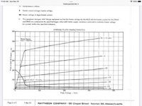
The graphs of harmonic distortion, and intermodulation distortion, are based on specific UL tap percentages, plate load, etc.
Many designers use circuits that they call UL, but they often are not adjusted for:
the minimum distortions, harmonic and intermodulation, which may or may not be at the same setup (plate load, UL tap percentage, etc.)
2. For quiescent screen voltages that are within their maximum limits . . .
with Pentodes and Beam Power tubes that are triode wired, the screens have the 'easiest duty'.
With Pentodes and Beam Power Tubes that are in Ultra Linear mode, the screens have 'medium duty'.
With 40% UL Tap, and the plate at 300V, and swinging down to 50V, the screen moves down 40% of 250V (100V swing), so the screen is at 200V when the plate is at 50V. Generally not a severe condition.
with Pentodes in pentode mode, and Beam Power tubes in Beam Power mode, the screens have the 'most severe duty'.
A screen at 300V, and a plate that swings from 300V down to 50V, will cause very high screen currents (screen at 300V and perhaps 50mA).
for sine waves, it only spends a little time there, duty cycle is low, so OK;
But hit it with very hard clipping, and it spends 50% of the time at 300V x 50mA = 15 Watts; at 50% duty cycle that is 7.5 Watts, lots more than some screens can take.
the first example of screen ratings of Beam Power tube I saw was the 807.
Beam Power mode, screen 300V max.
Triode Wired mode, screen 400V max.
I estimate that an 807 with a 50% Ultra Liner Tap might be OK with the screen at 350V quiescent.
Your Mileages May Vary
Correct.
1. UL designs do not have a constant screen voltage.
But, the screen voltage does move at a specific Percentage of the Plate Voltage voltage change.
The graphs of harmonic distortion, and intermodulation distortion, are based on specific UL tap percentages, plate load, etc.
Many designers use circuits that they call UL, but they often are not adjusted for:
the minimum distortions, harmonic and intermodulation, which may or may not be at the same setup (plate load, UL tap percentage, etc.)
2. For quiescent screen voltages that are within their maximum limits . . .
with Pentodes and Beam Power tubes that are triode wired, the screens have the 'easiest duty'.
With Pentodes and Beam Power Tubes that are in Ultra Linear mode, the screens have 'medium duty'.
With 40% UL Tap, and the plate at 300V, and swinging down to 50V, the screen moves down 40% of 250V (100V swing), so the screen is at 200V when the plate is at 50V. Generally not a severe condition.
with Pentodes in pentode mode, and Beam Power tubes in Beam Power mode, the screens have the 'most severe duty'.
A screen at 300V, and a plate that swings from 300V down to 50V, will cause very high screen currents (screen at 300V and perhaps 50mA).
for sine waves, it only spends a little time there, duty cycle is low, so OK;
But hit it with very hard clipping, and it spends 50% of the time at 300V x 50mA = 15 Watts; at 50% duty cycle that is 7.5 Watts, lots more than some screens can take.
the first example of screen ratings of Beam Power tube I saw was the 807.
Beam Power mode, screen 300V max.
Triode Wired mode, screen 400V max.
I estimate that an 807 with a 50% Ultra Liner Tap might be OK with the screen at 350V quiescent.
Your Mileages May Vary
Last edited:
Only in the sense that the extra load drops B+ a bit. There is a cap between the tubes so the DC conditions of one do not influence the other.If there is no current draw on the driver tube would that affect the output tube also?
I.e. if I can get the 6n1p to draw current that could be the solution?
Just thought to ask if that is potentially only part of the problem.
Jan
There is a cap between the tubes so the DC conditions of one SHOULD not influence the other.
Do you have any voltage on pin 5 of the output tubes??
Do you have any voltage on pin 5 of the output tubes??
For pentode operation, especially if you’re going to beat on it, high perveance sweep tubes seem to make more sense that typical ‘audio’ tubes. You can often get enough plate current with only 100-150v on the screen, and the ratio of plate to screen current it often higher than in typical audio tubes. Here if you needed the same 400 mA afforded by a KT88 or EL34 only 110 on the screen is needed. Even operating below the knee, you’d only draw 100 mA screen at full square wave clip - and the resulting 5.5 watts g2 dissipation would be within rating. Even with NO LOAD you’d be within the 12 watt intermittent rating, (assuming you’ve clamped the overvoltage somehow, separate issue). If you’re having to run the screen up at 300,400 volts just to get enough plate current that ain’t gonna happen. And you melt screens.with Pentodes in pentode mode, and Beam Power tubes in Beam Power mode, the screens have the 'most severe duty'.
A screen at 300V, and a plate that swings from 300V down to 50V, will cause very high screen currents (screen at 300V and perhaps 50mA).
for sine waves, it only spends a little time there, duty cycle is low, so OK;
But hit it with very hard clipping, and it spends 50% of the time at 300V x 50mA = 15 Watts; at 50% duty cycle that is 7.5 Watts, lots more than some screens can take.
Attachments
Before I do a few more tests and respond to dubadub and mike567' posts, could I just quickly ask:
Would it be ok to take all tubes out, including rectifier, to do a heater check?. These are underneath my board so I would do the test using the pins on top of the chassis.
Valves are warm after a few seconds, but would like to check it's the heaters.
Would it be ok to take all tubes out, including rectifier, to do a heater check?. These are underneath my board so I would do the test using the pins on top of the chassis.
Valves are warm after a few seconds, but would like to check it's the heaters.
yes. with no rectifier tube installed, there will be no DC voltage in the circuit. and remember, unloaded heater supply will show closer to 8v.
Check RobRob's page on Amp Startup
w
Check RobRob's page on Amp Startup
w
That's great thank you, you are being very helpful really going out of your way. I'm very thankful.
- I will test heaters,
- see if I can hear tapping noises on pin 3 of the output tubes (all valves inserted),
- measure pin 5 of the output tubes,
- measure plates on the 6n1p and then the cathodes.
yes. with no rectifier tube installed, there will be no DC voltage in the circuit. and remember, unloaded heater supply will show closer to 8v.
Check RobRob's page on Amp Startup
w
OK so,
I've tested all the heaters, they are all OK 6.5v ac.
I've checked each and every ground return and they are all OK. (I couldn't check the 33uf cap though).
Switched on to test and the voltage shot up to over 540v (!) on pin 1 of the 6n1p so switched off in a panic.
The voltage is reducing very slowly, after a few minutes after power off:
- voltage on both KT66's and 6n1p plates are the same at 385v and B+ is at 385v also (before the 4.7k resistor).
- the cathodes on the KT66's are only a few Mw and reduce to 0v when I place + probe on pin 8.
The cathodes on the 6n1p are both between 200 - 300mV and are increasing when I place my probe on pin 3 (or 8).
It is very frustrating I don't have much time to check any reading for fear of this ever increasing voltage.
540v and it was still rising, my Mains Tx is 750v CT which = 375v x 1.414 = 530v max (?)
I dare not do any tapping of pins at the moment which again is frustrating and doesn't provide any feedback for trouble shooting. This is some Rodeo.
Last edited:
A Variac would be a worthwhile investment at this point.
Or wire an incandescent bulb in series with the mains to lower the xformer voltages.
The heaters will also be lowered, but a decrease of 10-20% will not harm for testing and will lower B+ to be safe for the elcaps.
Jan
Or wire an incandescent bulb in series with the mains to lower the xformer voltages.
The heaters will also be lowered, but a decrease of 10-20% will not harm for testing and will lower B+ to be safe for the elcaps.
Jan
So current is not flowing thru the tubes. Can't be. B+ to filter caps to OPT to anode to cathode resistor to ground. There a broken link in there.
Your amp suffered a catastrophic failure, how many of those parts are still in the amp? Did the cathode resistors fail open? I imagine they got awfully warm being fastened to wood...
Agree. Question: is the B+ measured dirctly on the tube anode or somewhere else like on the output xformer?So current is not flowing thru the tubes. Can't be. B+ to filter caps to OPT to anode to cathode resistor to ground. There a broken link in there.
Where's the ground lead of the meter connected, to the bottom of the cathode R or somewhere in the power supply?
Also, what's the screen voltage when powered up?
Jan
- Home
- Amplifiers
- Tubes / Valves
- KT88SE - with EL34s