A 470k resistor is a Very Poor B+ Bleeder Resistor for a vacuum tube power amplifier.
Safety First!
Prevent the "Surviving Spouse Syndrome".
A 470k resistor, and total of only 100uF filter capacitors, has a time constant of 47 seconds.
A 100uF capacitor capacitor that is charged to 400V will be reduced by 63% of 400V in 47 seconds (148V at the end of 47 seconds . . . Ouch!)
I use two 25k 5 Watt resistors in series (10 Watts total).
At 400V, each resistor dissipates 1.6 Watts (3.2 Watts total).
50k resistance total, and 100uF has a time constant of 5 seconds (148V at the end of 5 seconds).
After 5 seconds more, the voltage discharges an additional 63%. Now, at 10 seconds Total, the voltage is only 54.8V.
One more time constant (5 seconds), the 63% voltage reduction takes us to 20.3V.
Turn the amplifier off, and remove the power cord.
If you take 15 seconds to remove the bottom cover from the amplifier, you are safe, at 20.3V.
Suppose you have 300uF total B+ filter capacitance, you need 3 x 15 seconds, (45 seconds to get to 20.3V).
Example of the total capacitance I am talking about is this . . .
CRCRC filter: 50uF, 100 Ohms, 125uF, 1k Ohms, 125uF (300uF total).
Stay Safe!

Thanks, 47 seconds is fine, I used two DMM's yesterday which took around 6hrs to get to 0v (!)
I do, however, have 39k 9w resistors spare which I use for the 6n1p plates, I will use those, in series.
Safety wise, I am really cautious, not educated in electronics as such but I am aware of the risks. Safety kit includes rubber gloves, double insulated DMM probes, Safety goggles, ear defenders, rubber shoes and a Co2 fire extinguisher.
Attachments
Last edited:
Hi all,
Hope this strand will still being read.
So, having had a busy spell at work gave me the chance to step back a bit and have a think about safety.
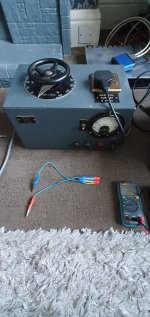
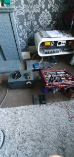
So, made a set of bleeder resistors, 8R dummy load and bought a variac. As attached.
The bleeder resistors are 39k 9w in series and work very well and quickly, getting only mildly warm. The variac is great, 1950's Claude Lyons which is a very reputable manufacturer here in the UK.
Having all this now has allowed me to take the following measurements, and quite comfortably too with not too much in the way of shacking hands and sweating.
First test was at 140v ac, which was when it started to come into life.
Test 1:
Plate voltage: 262vdc
6n1p plate: 165v/154v
6n1p Cathode: 1.81v/1.86v
KT66 Cathode: 12.7v/13.00v
Test 2:
Plate voltage: 325v
6n1p plate: 169v/164v
6n1p Cathode: 2.15v/2.18v
KT66 Cathode: 28.4v/29.2v
First thing I notice was there was a drop in voltage between B+ and 6n1p plate which didn't happen before.
The only thing I have done to this circuit since last post was to remove the 6n1p cathode led and resistor on both channels. I thought the led may have failed but they hadn't, so re-installed them and undertook the testing as above. Maybe, there was a bad joint here? Bit of luck if that was the case.
Those readings look OK ok to me, any thoughts? Maybe the KT66's cathodes are a little high. Using Rob Robinettes calculator, and using the original plate voltages with the KT88's, the cathode voltages should be around 33v.
The original plates (KT88) were at 425v so another 100v dc to go on the plate of the KT66 but only another 4v remaining on the cathodes before they will be overdriven.
Hope this strand will still being read.
So, having had a busy spell at work gave me the chance to step back a bit and have a think about safety.
So, made a set of bleeder resistors, 8R dummy load and bought a variac. As attached.
The bleeder resistors are 39k 9w in series and work very well and quickly, getting only mildly warm. The variac is great, 1950's Claude Lyons which is a very reputable manufacturer here in the UK.
Having all this now has allowed me to take the following measurements, and quite comfortably too with not too much in the way of shacking hands and sweating.
First test was at 140v ac, which was when it started to come into life.
Test 1:
Plate voltage: 262vdc
6n1p plate: 165v/154v
6n1p Cathode: 1.81v/1.86v
KT66 Cathode: 12.7v/13.00v
Test 2:
Plate voltage: 325v
6n1p plate: 169v/164v
6n1p Cathode: 2.15v/2.18v
KT66 Cathode: 28.4v/29.2v
First thing I notice was there was a drop in voltage between B+ and 6n1p plate which didn't happen before.
The only thing I have done to this circuit since last post was to remove the 6n1p cathode led and resistor on both channels. I thought the led may have failed but they hadn't, so re-installed them and undertook the testing as above. Maybe, there was a bad joint here? Bit of luck if that was the case.
Those readings look OK ok to me, any thoughts? Maybe the KT66's cathodes are a little high. Using Rob Robinettes calculator, and using the original plate voltages with the KT88's, the cathode voltages should be around 33v.
The original plates (KT88) were at 425v so another 100v dc to go on the plate of the KT66 but only another 4v remaining on the cathodes before they will be overdriven.
Attachments
I am not sure what your schematic parts values are now; but I think your KT66 cathode self bias resistor is 500 Ohms, Right?
29.2V / 500 Ohms = 58.4mA That current is the total of plate and screen current.
Plate at 325V
325V - 29.2V = 295.8V plate to cathode
295.8V x 0.0584A = 17.2 Watts . . . Looks like the KT66 is safe.
What parts in the KT88 version had values that changed when you went to the KT66 Version?
Why was the plate voltage on the KT66 325V . . . when it was 425V for the KT88s.
The KT88 transconductance changes at the rate of 11.5 mA per volt of self bias.
The KT66 transconductance changes at the rate of 6mA per volt of self bias.
Perhaps, with the same 500 Ohm self bias resistor, the KT88 is a lighter load on the B+.
Could that explain, at least in part, the higher B+ with the KT88.
Last edited:
Yes, of course, thank you for your reply.
The plate voltage of 325v was because I was using the variac and limiting the total amount of incoming AC, simply for testing purposes. So, if I take the variac out and use the mains direct, plates will be 425v.
The KT66 Cathode self bias resistor has been changed from 500 ohms to 570 ohms and this is the only change in the schematic.
With the 570R bias resistor and 325v plates (testing) the tubes are dissipating a little less at 13.8w, 55% plate dissapation.
Next test will be turn the variac higher, closer to the 425v, interesting to see what the cathode voltage will be, I may need to increase the resistor further.
Separately, if you recall, I had a lot of troubles before I bought the variac. The voltage kept rising, the tubes were not conducting and there was no voltage drop after the plate resistors.
This has now sorted itself out. I didn't know what the problem was before and I don't know how it was fixed which isn't very helpful, I took out 6n1p bias led and resistor and re-installed them and everything appears to be working OK. I did check before that they were connected to the driver pins 3 and 8 and then checked, by measurement, they were connected to ground and they were.
Bit of a head scratching mystery as to why this would be.
Watch those KT66 tubes. I really like them.
KT66
Plate max 25 Watts
Screen max 3.5 Watts
But, you are not allowed to use the sum of 25 + 3.5 = 28.5 Watts, too hot!
The max combined rating is only 27 Watts.
Do not forget, there already is another 8.19 Watts of heat in the filament.
8.19 + 27 = 35.19 Watts of real hot glass!
Give space around the tubes; do not put something hot next to them, like an overburdened power transformer, or a power resistor, etc.
I'm aiming, with tweaking of the cathode bias resistor, to get around 80-85% plate dissapation (say 21w) and using Rob Robinettes calculator.
Not too sure how to measure the screen dissaption. I do have a 100ohm resistor between the screen grid (pin 4) and UL tap but cannot access them as they are underneath the board.
Is screen dissapation a general requirement for testing, in addition to plate dissapation?
Not too sure how to measure the screen dissaption. I do have a 100ohm resistor between the screen grid (pin 4) and UL tap but cannot access them as they are underneath the board.
Is screen dissapation a general requirement for testing, in addition to plate dissapation?
For Ultra Linear operation, start by making sure that the screen voltage is within its maximum voltage specification.
If the voltage is within limits; and if the plate dissipation is in limits, the screen dissipation is probably OK (bias volts that makes the plate dissipation OK, will usually be enough bias voltage to keep the screen dissipation, if the screen voltage is within its max limits.
The screen voltage will be higher than the plate voltage, because of the DCR of the UL tap to the plate tap windings, that DCR times the plate current = the voltage drop at the plate.
Usually, when a part us underneath a PCB, you can use sharp DMM leads to "stab" through the traces, or stab on the solder points of the screen resistor.
With the amplifier turned off, power cord removed, and capacitors discharged, Measure the screen resistor, Rs, Ohms.
With the amplifier on, measure the voltage across Rs.
Measure the screen voltage (just measure the UL Tap voltage, that is close enough unless something is very bad, like a screen to ground short, or a very high resistance screen resistor).
Voltage across Rs / Rs Ohms = screen current.
Screen current x screen volts (UL Tap voltage) = screen quiescent dissipation.
If there is not a lot of voltage drop from the UL Tap to the Plate Tap, and the UL Tap voltage is less than the screen maximum specification,
It is probably OK.
According to Murphy's law, the one thing that you do not check is what will cause Murphy's worst to happen.
Just a pessimist's view point.
Last edited:
I can't get beneath the board I'm sorry to say so I'm hoping Murphy will be OK with that.
I've made some voltage measurements for my amp (AC was not quite 230v but 226v) and the 6n1p dropper resistor (top of the 39k resistor) measures 395v and the plate (bottom of the same resistor) measures 179v.
So 6n1p bias is 395v - 179v = 216v/39 = 5.54mA which is ideal.
The KT66 however, using Rob Robinettes calculator, has a plate of 414v and a cathode of 36v, which equates to a bias of 64.3mA and 92% plate dissapation.
This is too hot so, going back to the first post which seams ages ago, a 560ohm cathode bias resistor is too low for a KT66 in this circuit.
Both KT66'S have the same plate voltage of 414v and both tubes are a matched pair. There is a difference of 5ohms in the bias resistor and this has the effect of having a 2% difference in plate dissapation (92%/94%).
So, I think the next resistor valve will be 600ohms or 620ohms. Maybe 680R will be too much, I'm aiming for a relatively cool 80% dissapation.
Class A can run 100% no problem. you're burning up that cathode oxide if the amp is on, might as well run the tubes flat out. not like Fixed-bias P-P where you want 60% bias.
And putting a much bigger Kr in there will reduce the current coming out of your power supply, which will make the b+ voltage higher. Do you already have a resistor dropping some voltage in the power supply? 50-150R just after the first cap can bring the b+ down a bit...
And putting a much bigger Kr in there will reduce the current coming out of your power supply, which will make the b+ voltage higher. Do you already have a resistor dropping some voltage in the power supply? 50-150R just after the first cap can bring the b+ down a bit...
Hi dubadub, welcome back!
OK, well, I was reading Robinettes calculator he states 90% being the max safe dissapation.
I would have thought 600R would be ok, just a little adjustment. I did replace original 500R with the 560R and this has made little difference to b+.
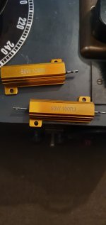
I haven't added dropping resistors to the power supply yet, but I can do that. I have 100R 50w power resistors as attachment if these would do? I assume you mean after the first cap being the 10uf cap, before the choke/inductor and before the first electro? These, I think would generate a lot of heat? I could mount them on the top plate which is already fairly warm.
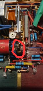
Finally, if you recall I had a big gremlin with rising b+ and tubes not conducting? (And with your help and guidance) I got my newly acquired variac and (I think) I had a cold joint as the 2nd attachment. For some reason the 6n1p cathodes measured resistance but were not actually conducting in circuit (?).
Thanks!
OK, well, I was reading Robinettes calculator he states 90% being the max safe dissapation.
I would have thought 600R would be ok, just a little adjustment. I did replace original 500R with the 560R and this has made little difference to b+.
I haven't added dropping resistors to the power supply yet, but I can do that. I have 100R 50w power resistors as attachment if these would do? I assume you mean after the first cap being the 10uf cap, before the choke/inductor and before the first electro? These, I think would generate a lot of heat? I could mount them on the top plate which is already fairly warm.
Finally, if you recall I had a big gremlin with rising b+ and tubes not conducting? (And with your help and guidance) I got my newly acquired variac and (I think) I had a cold joint as the 2nd attachment. For some reason the 6n1p cathodes measured resistance but were not actually conducting in circuit (?).
Thanks!
Attachments
***I could also install both 100R's in series?
First 100R, then if need be, try 200R.
I'll try both of these on Wednesday firstly, keeping the 560R bias resistors.
Will let you know how this affects tube dissapation then...
First 100R, then if need be, try 200R.
I'll try both of these on Wednesday firstly, keeping the 560R bias resistors.
Will let you know how this affects tube dissapation then...
Check out the Power Supply for the Lacewood 2.0. there's a 350ohm 5w resistor between the first cap and the first choke. Those big resistors you have are a bit over-rated, 5w is ok, but you'll see the drop. If you measure the voltage drop across that resistor and divide it by the value of the resistor, you'll find the amps flowing thru the resistor, something between 0.15-0.2A.
I think you've biased the tubes just fine and you should relax and have a listen. Of course the KT66 tubes are going to run hotter than KT88 in the same amp, changing cathode resistors doesn't change the output of the power transformer.
I think you've biased the tubes just fine and you should relax and have a listen. Of course the KT66 tubes are going to run hotter than KT88 in the same amp, changing cathode resistors doesn't change the output of the power transformer.
Run an output tube at whatever load impedance and dissipation that gives you the results compromise you want, power, distortion, reliability, fireworks, etc.
Don't tell some of the Guitar Amplifier Engineers to keep the dissipation at 90% maximum.
Some Guitar players have amplifiers that will blow up in the middle of a gig, so that they can go home early.
I have never personally heard the blowout, I always get to the gig a little late, Darn!
Don't tell some of the Guitar Amplifier Engineers to keep the dissipation at 90% maximum.
Some Guitar players have amplifiers that will blow up in the middle of a gig, so that they can go home early.
I have never personally heard the blowout, I always get to the gig a little late, Darn!
dubadub,
The power transformer does not change the power out (except if you change the primary impedance, that changes the load line slope).
KT88 and KT66
The quiescent power in those tubes is determined by:
Plate voltage, bias voltage (or self bias voltage in this case), and the Screen voltage (screen voltage level affects the plate current, for a given bias voltage).
KT88 transconductance about 11.5mA/V bias, u = ~ 8
KT66 transconductance about 6mA/V bias, u = ~ 8
For a given plate volts, screen volts, and a fixed self bias resistor:
The KT88 will draw less current than the KT66.
The KT88 filament heat is 6.3V x 1.6A = 10.08 Watts
The KT66 filament heat is 6.3V x 1.3A = 8.19 Watts
Even if there is No B+ to the plate and screen, the tube will get warm.
If you set the KT88 plate dissipation to be equal to the KT66 plate dissipation, the KT66 plate will get hotter than the KT88 plate.
Curious?
The KT88 has more fins that better radiate heat to the outside world, versus the KT66 lower number of fins.
Tubes can be mysterious, until you know more.
100R resistor installed between first cap and inductor/choke and tested with variac.
All was well at test voltage of 260v dc showing around a 20v drop over the resistor. Then, OL registered on the multimeter and the voltage dropped in and out a few times, before dropping to about 5v.
Crackling sound so switched off (!)
Obviously a dodgy joint again I checked the resistor end adjoining pin 8 of the rectifier and that was 0v so looks like pin 8 has the bad joint (not too sure if bad joint would crackle though). I did push and pull the rectifier heater cable to get the resistor in so maybe that.
No need to post this but some newbie like me may read this and see even simple mods can be a bit troublesome, doesn't help rushing and being in a bad mood either.
Will have to leave till tomorrow...
Hi all,
I managed to resolve the issues, to a certain point, and have been using this great sounding amplifier for a couple of weeks.
Attached is my (bit ropey) schematics and voltage measures.
Listening one evening, after a couple of hours, the rectifier gave out a bright flash and loud pop. I thought that I needed a new rectifier and ordered a new one, 5u4g, same as previous.
At the same time I thought to replace the 6n1p.
With the new tubes installed I tested all the measurements again and the 6n1p plate had the 170v reading on one channel, as previous, but the other channel had risen to 184v. Still sounding excellent.
Yesterday, after about an hour and after a few days of use, the rectifier flashed again but with a not so loud pop. Still playing, sounding excellent, fuse OK.
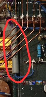
Could the first time the flash and pop occured have caused the electro (between the 39k and 4.7k resistors) to short on one channel, which is why one of the 6n1p plates is 14v higher than the other?
Can a well used rectifier flash and pop?
Can it cause an electro to short?
If so, can the shorted electro cause a new rectifier to flash and pop.
All the voltages and the cap values etc seem fine to me so I can only think the flash and pop, originally, was due to approx 7500hrs of use.
I managed to resolve the issues, to a certain point, and have been using this great sounding amplifier for a couple of weeks.
Attached is my (bit ropey) schematics and voltage measures.
Listening one evening, after a couple of hours, the rectifier gave out a bright flash and loud pop. I thought that I needed a new rectifier and ordered a new one, 5u4g, same as previous.
At the same time I thought to replace the 6n1p.
With the new tubes installed I tested all the measurements again and the 6n1p plate had the 170v reading on one channel, as previous, but the other channel had risen to 184v. Still sounding excellent.
Yesterday, after about an hour and after a few days of use, the rectifier flashed again but with a not so loud pop. Still playing, sounding excellent, fuse OK.
Could the first time the flash and pop occured have caused the electro (between the 39k and 4.7k resistors) to short on one channel, which is why one of the 6n1p plates is 14v higher than the other?
Can a well used rectifier flash and pop?
Can it cause an electro to short?
If so, can the shorted electro cause a new rectifier to flash and pop.
All the voltages and the cap values etc seem fine to me so I can only think the flash and pop, originally, was due to approx 7500hrs of use.
Attachments
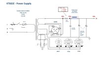

Thanks for the reply, it is a total of 200uf.don't know how to run the numbers but 400uF after the choke seems like an awful lot. That rectifier tube is having to fill that big tank as soon as it's conducting. Might be worth going down to 100uF after the choke.
2nr caps, each having 2nr 50uf tags, (50uf x 4nr total - 200uf).
This is the same set up, and caps, I've been using for the past two years with no issue (with KT88's). The flashes occured after 1-2 hrs of use.
- Home
- Amplifiers
- Tubes / Valves
- KT88SE - with EL34s